Painting spinning mechanism for artist Nadia Shinkunas
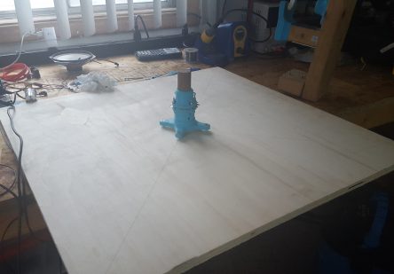
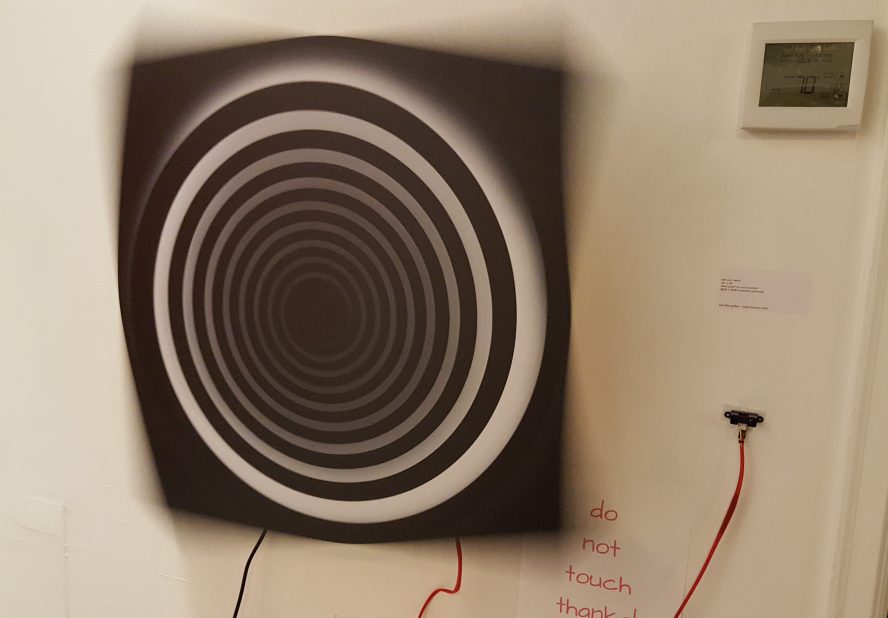
Earlier this year I was commissioned by the artist Nadia Shinkunas to design and build a way to spin one of her paintings at different speeds based on the position of the observer. Using CAD, 3D printed parts, bicycle components, off-the-shelf electronics and a distance sensor I was able to rapidly design, prototype and fabricate a robust mechanism that held up for the length of the exhibit and beyond.
Table of contents
Source code, design files, and other supporting documents
All of the ready-to-print 3D models, Arduino firmware, component datasheets, and other source files are available for free over at the following Github repository. Please feel free to build, remix, and play around however you’d like, so long as you follow the license below!
All of these files are released under the Creative Commons Attribution-NonCommercial-ShareAlike license, which means you are free to use the files so long as you (1) link to me in some way as the author of the original work and (2) don’t use it to make money.
Bill of materials (BOM)
Mechanical system
When one thinks of making something spin, the natural implication is that there is a motor involved. I began my design process with this implication, which led me to ask some basic questions about the load it would be expected to move, and how quickly it needed to move it.
Nadia knew the approximate dimensions and weight of her painting, as well as the maximum and minimum speeds she was expecting (the words “woosh woosh” came up quite a bit in these conversations). From here I could do some calculations to figure out the necessary torque requirements for the DC motor and hunt down a suitable motor from a supplier.
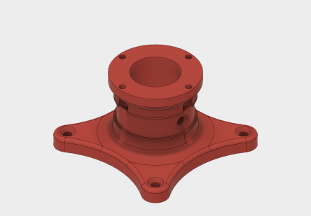
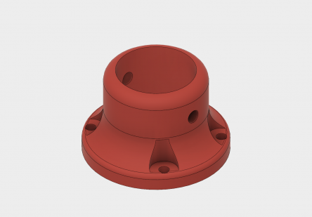
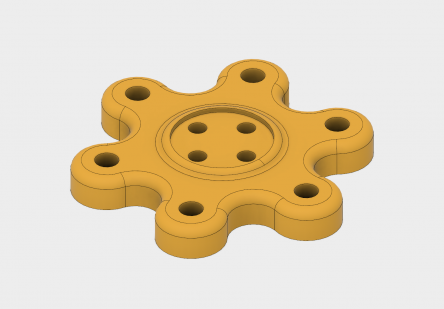
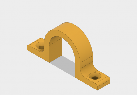
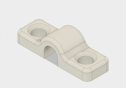
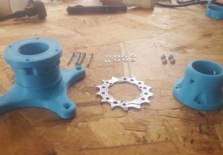
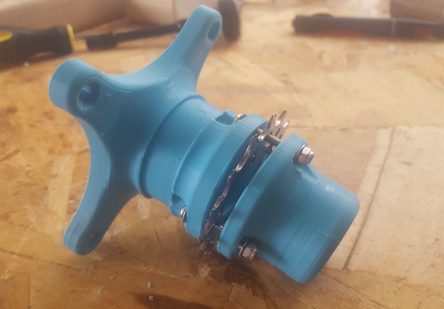
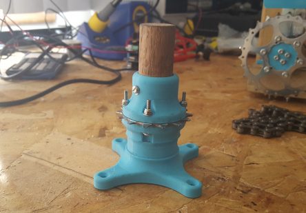
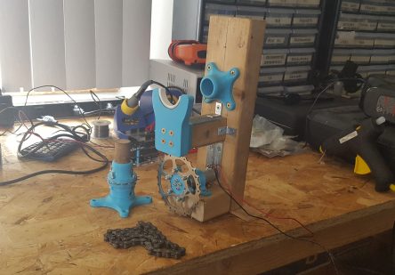
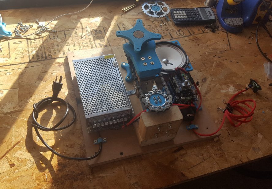
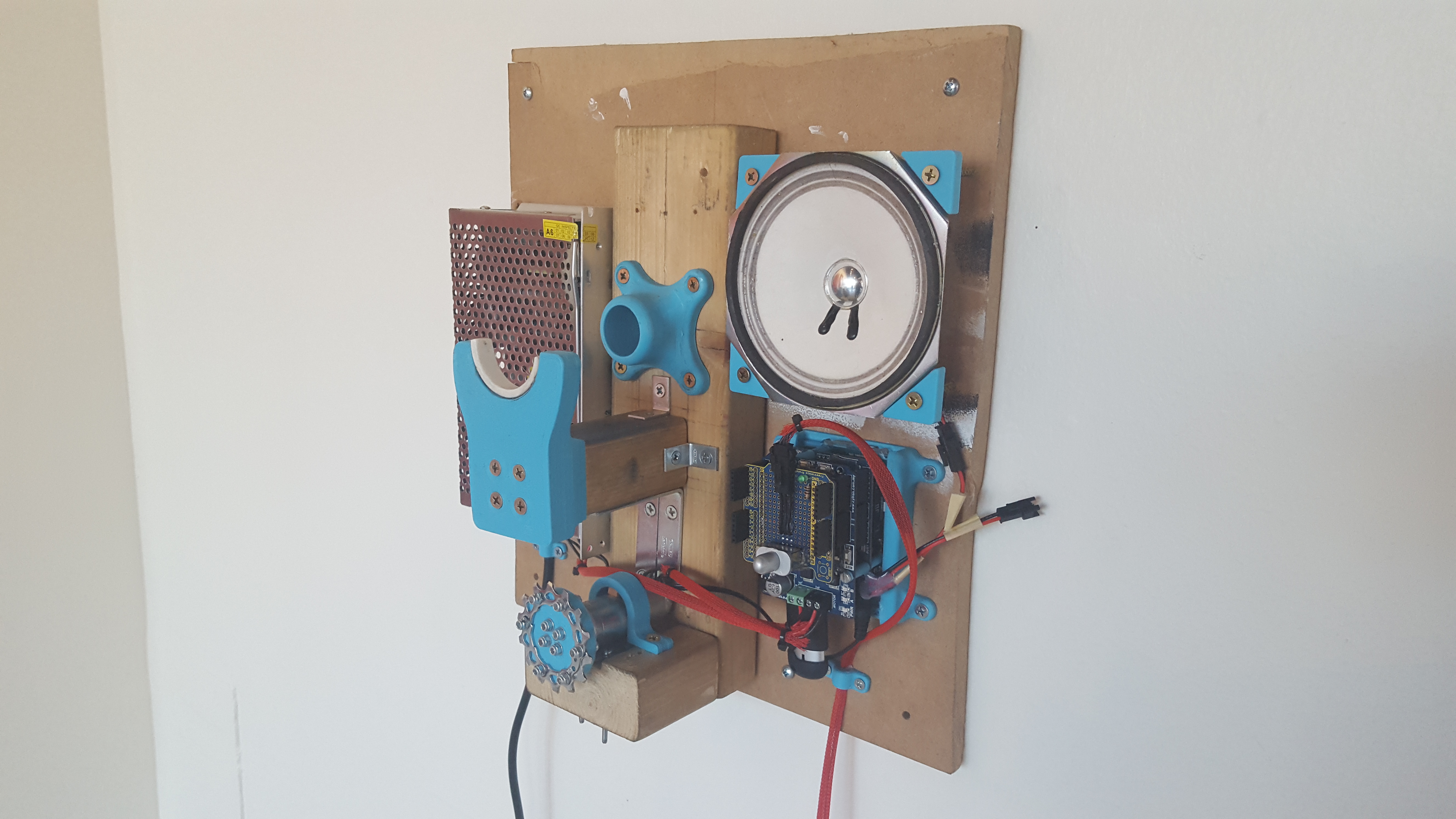
I chose to mount the painting to a spinning shaft that is physically decoupled from the shaft of the motor such that the weight and momentum of the painting don’t cause too much wear on the internal bearings or assembly of the motor, especially during transportation or storage. This shaft is supported by a 3D-printed part with a small section of PVC pipe that helps tremendously to reduce friction, allowing the motor to start spinning from a cold stop much more easily and significantly minimize wear-and-tear.
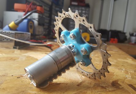
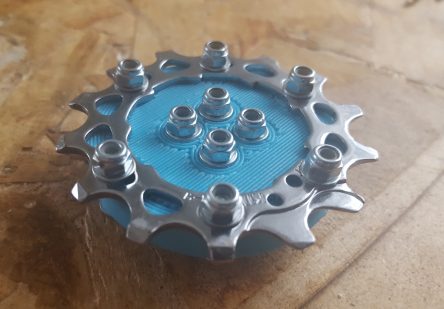
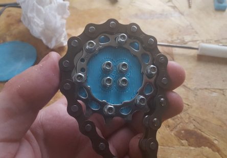
To mechanically couple the shaft for the painting the motor I chose to use bicycle chain and sprockets for their durability and strength. Specifically I used a pair of 14-tooth sprockets along with appropriate chain, all of which were acquired from the Community Bike Project and Olympia Cycle in Omaha, NE.
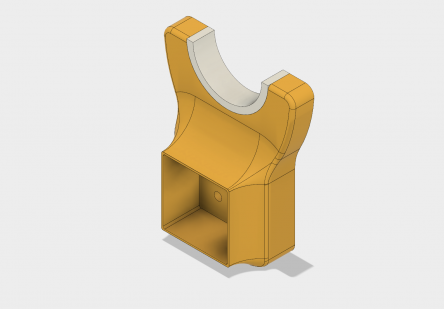
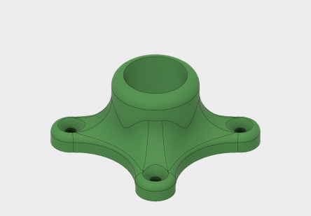
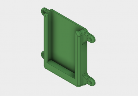
Once I knew the dimensions of the motor and the various bicycle components for the drive system I was able to design all other parts based on simple and obvious functions – support structures, mounting adapters, connectors, etc.
Design
All parts were designed in Fusion 360, which not only provided an extremely quick and powerful way to create the parts themselves, but also to visualize and analyze how it would all fit together and move. This project would have taken much longer and been of a poorer quality if it weren’t for this wonderful piece of software!
Fabrication
![]() All custom parts were 3D printed on my personal Rostock MAX V2 using a lovely light blue ABS with print settings optimized for part strength (3 perimeters and 40% infill). A small amount of iteration was required for some of the major parts (usually about 3 rounds), though the entire process only took about a week a half to two weeks.
All custom parts were 3D printed on my personal Rostock MAX V2 using a lovely light blue ABS with print settings optimized for part strength (3 perimeters and 40% infill). A small amount of iteration was required for some of the major parts (usually about 3 rounds), though the entire process only took about a week a half to two weeks.
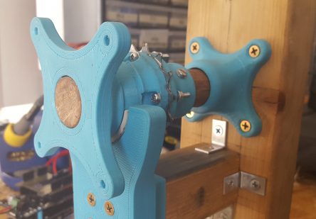
While the custom parts were being 3D printed I put together the mounting structure using scrap wood and construction screws. The only things I needed to actually go and buy myself were the screws and a wooden dowel!
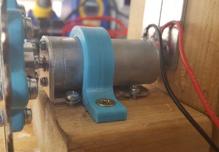
All of the various bicycle drive system components and 3D printed parts were assembled using metric fasteners, with some parts being rigidly affixed to the wooden support structure using wood screws.
Electronics system
Nadia had two requests for this piece – (1) that the painting spin in response to the position of a nearby observer, and (2) that it would be even cooler if there was an interactive audio component.
As an engineer I have a tendency to make things difficult for myself by designing and fabricating everything custom. Sometimes that is appropriate, and sometimes its not. In this case I knew exactly what I needed to build and how I would build it – but was it worth doing it all myself? With all the CAD and physical prototyping work to be done, I didn’t think so.
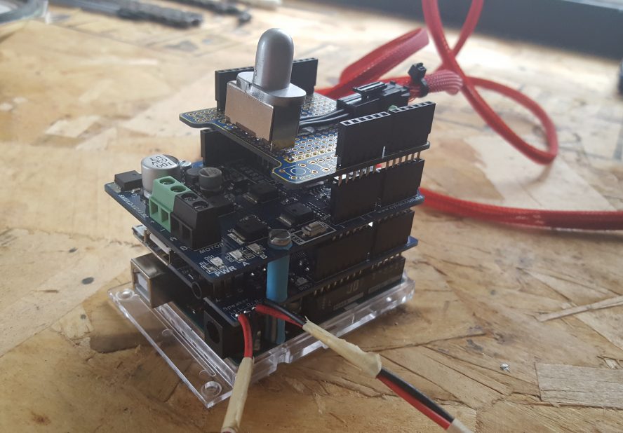
Therefore I decided on using the Arduino shield ecosystem to handle all of my circuitry needs, relying on a Chinese maker brand to keep costs low. The stack of shields and their various functions and connections are as follows:
Design
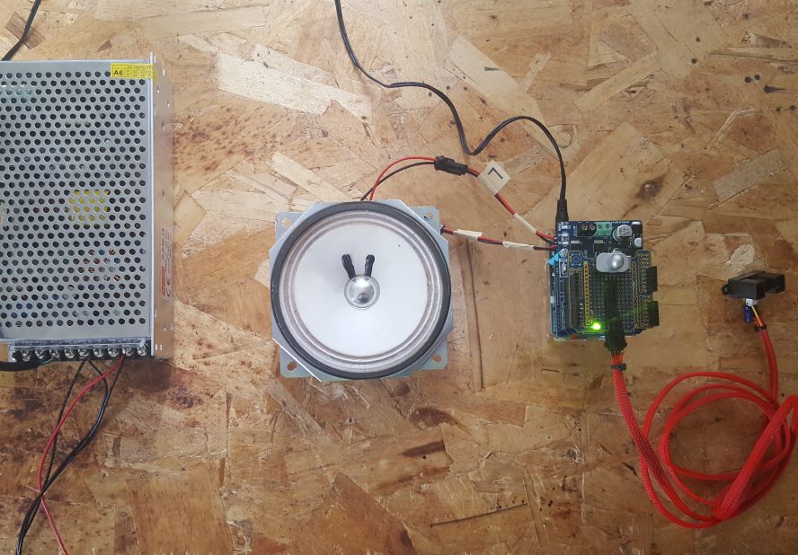
Using an Arduino Uno as the base system, nearly all required functionality was achieved through the use of simple manufactured shields. Specifically, one shield was dedicated to allowing robust control of the DC motor via a sufficiently powerful H-bridge, while another was dedicated to audio output (which was not used in the final version due to time constraints).
A prototyping shield at the very top of the stack allowed me to add a quick-release 3-pin JST SM jack and plug for an infrared distance sensor, making any future maintenance or replacement easier.
A dedicated 12V power supply was also integrated into the design in order to supply sufficient power for the DC motor while also powering the Arduino Uno via it’s on-board barrel jack.
Fabrication
One of the major benefits of the Arduino shield architecture is that assembly is as simple as just stacking circuit boards on top of each other – no soldering required! Well, almost no soldering. The top-most shield is a blank prototyping shield that allows me to create any kind of circuit I want, to which I added a 3-pin JST quick-connect jack, a large on/off slide switch and an LED to indicate power.
Programming and testing
While assembling the electronics system I tested each component using small, focused Arduino sketches. Once I could see that each component was in good working order I needed to write a bit of code to map the data from the distance sensor into rotational speeds for the DC motor.
Given the relatively large size and weight (and therefore large moment of inertia) of the painting, the motor needed to make all of its speed adjustments very gradual, especially from a dead stop. Therefore I thought it would be best not to directly map the distance sensor data to the motor’s speed, but rather map this data to a “target” speed that the motor would be perpetually chasing at it’s own pace. This meant that the motor could have it’s own acceleration parameters that are independent of whatever the distance sensor is doing, enabling it to respond to interactions at it’s own safe pace.
The final sketch, as well as the various calibration sketches I used, are all available on the project’s Github repository.
Installation
The mechanism was installed at the Little Gallery & Benson Underground Film Forum in the Benson neighborhood of Omaha, NE along with several other works by the artist. The exhibition ran for one month, throughout which the spinning mechanism continued to function as expected.

