Electronics design for Eyewriter 2.1 open-source eye-tracking system
This past weekend I sent away for the first round of circuit boards (PCBs) to be fabricated for the Eyewriter 2.1 eye-tracking system, marking the first major milestone for the electronics system! The updates on this project have been a little on the light side because I’ve been working almost completely on this! Hopefully this post will make up for the lack of updates!
About the Eyewriter 2.1 project
Eyewriter 2.1 is an updated version of the Eyewriter 2.0 open-source eye-tracking system. It uses a modified PS3Eye webcam and flashing LEDs, along with specialized software, to track the position of a user’s pupil. Pupil position is then translated into useful actions like moving the mouse to draw on the screen. It consists of three major subsystems:
- Electronics – infrared LEDs that pulse in sync with the camera’s frame rate to flash light onto the user’s pupil.
- Hardware – a physical platform for the electronics to attach to, which is currently being developed and will be written about very soon.
- Software – a set of openFrameworks programs that track the user’s pupil position using the reflections from the flashing infrared LEDs.
In this post, I’ll just be talking about the electronics system. Specifically, the first version of the circuit boards that I’ve designed as an update to the original project.
The original version of this project is meant to be completely built from scratch out of easily-sourced parts, it requires quite a bit of electronics know-how to make and could be quite frustrating for non-electronics people. When I consider the intended audience, I feel that the project is just too difficult for many people to create. Therefore I set out to create a circuit board that can be manufactured for the user so that they would only have to plug in a couple of cables and tighten some screws to get a working system.
All of the source files for the electronics system can be downloaded for free from this project’s official Github repo at:
Overall design of the electronics system
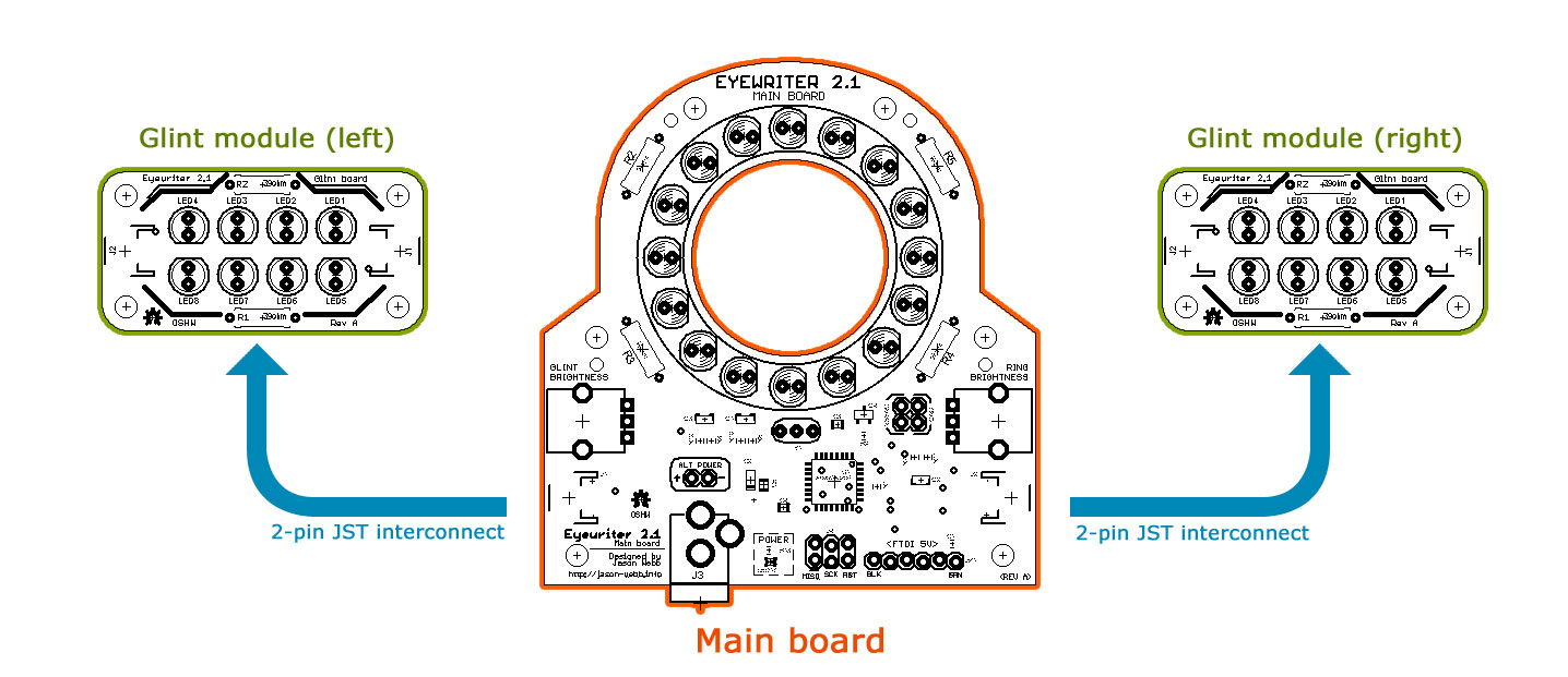
The electronics system serves one function and one function only: to flash a bunch of infrared lights in your face. When properly connected to a camera (I’m planning to use the PS3Eye camera), the circuit board will alternatively flash the LEDs on the two outer circuit boards (which I’m calling “glint modules”) and the LEDs on the main circuit board in sync with the frame rate of the camera.
To make things less ambiguous for the software, the glint module LEDs and the main board LEDs take turns flashing. For example, on odd frames only the main board LEDs light up, and on even frames only the glint module LEDs light up. From what I currently understand, the difference between the positions of the side reflections and the central reflection is indicative of the direction your eye is pointed. But don’t hold me to that!
When the LEDs on the two outer circuit boards (“glint modules”) flash, the camera will see two reflections on your eyeball – one on each side.
When the LEDs on the main circuit board flash, the camera will see your entire pupil light up evenly.
Custom desktop software (to be discussed in another blog post) will use these two types of reflections to identify the position of your pupil and convert that into useful actions like mouse movements.
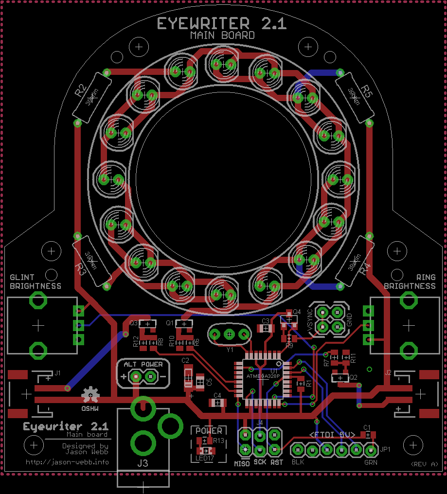
Closer look at the main board
The main electronics board contains a ring of infrared LEDs that pulse in sync with the frames of the camera. There is a large hole in the center, as well as small mounting holes on the sides of the ring, so that a PS3Eye (or other camera) can be attached with a couple of screws.
Board features
Microcontroller
The main board also contains an on-board ATMega328 loaded with the Arduino Uno bootloader and a custom Arduino sketch that simply flashes the LEDs.
Programming interfaces
There is both a 6-pin ICSP header for flashing bootloaders and raw AVR sketches, and an FTDI port for more “standard” Arduino reprogramming.
Power options
The board includes a standard DC barrel jack for use with wall adapters such as this one from Adafruit or this one from Pololu. Just above the power jack is a 2-pin header which can be connected to any power supply you want using simple jumper wires.
Brightness adjustment potentiometers
On both sides of the circuit board there are small potentiometers, which I intend to use to control the brightness of the LEDs. Right now I’m thinking of having one potentiometer to control both of the “glint modules” (see below) and the other to control the ring on the main board.
2-pin JST connectors to connect to glint modules
Also on each side of the circuit board is a 2-pin JST socket so that the two glint modules can be easily connected. I’m hoping this will make it easier for non-tech people to put the system together with minimal understanding of the electronics.
Vsync and ground inputs
To connect the camera to this main board, there are two sets of headers for “vsync” and “ground”. It is not super easy to modify the PS3Eye camera for vsync, but it must be done for the system to operate successfully. I’m hoping that in future, another camera can be found that offers the vsync connection with much less hassle, but for now that doesn’t seem possible.
Bill of materials
All of the electronic components for this circuit board can be purchased through Digikey. They offer very cheap and very fast shipping, as well as awesome price breaks when you buy in large quantities (there may be some Eyewriter 2.1 kits in the future ;)).
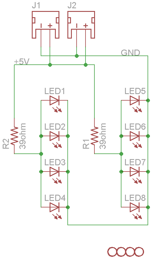
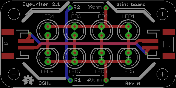
Closer look at the glint modules
 Separate from the main circuit board are a pair of small circuit boards containing LEDs that can be turned on and off by the main circuit board. These LEDs are meant to illuminate the sides of the user’s eye, creating “glints” that can be tracked by the software.
Each glint module board contains the footprints for two 2-pin JST connectors, but is only meant to have one populated at a time so you can use them on either side of the main board.
I’ve designed these boards to be so small that you can fabricate two of them for the price of one by using Seeed Studio’s PCB fabrication service. I’ve included a panelized PCB file in the Github repo!
Bill of materials
Like the main board, all of the parts for these modules can be purchased on Digikey.
Interconnects
To connect each of the glint modules to the main board I’ve opted to use 2-pin JST cables. The sockets are included in each of the board BOMs, but the actual cable itself is accounted for in this BOM:
Sending the board files off to be fabricated
On May 17th I placed an order through Seeed Studio’s Fusion PCB Service for 10 main boards and 20 glint modules, which should be enough to create 10 complete units (assuming I didn’t make any errors in the circuit design). Seeed provides a CAM file that you can use to easily export Gerber files, which are what the actual fabrication machinery uses to produce the boards.
Learn more about this project
To learn more about this project, first check my personal project wiki, where I try to aggregate all the information I publish and keep it all nice and simple. I also try to post as much as I can to the following places:
- All blog posts related to Eyewriter: https://jwwpheadless.com/tag/eyewriter
- Watch for activity on my Flickr collection: http://www.flickr.com/photos/zenwebb/collections/72157633266465369/
- All schematics, board design files, source code, BOMs and 3D files can be found at the official Github repo: https://github.com/jasonwebb/eyewriter
And watch for activity on my Github fork:
Next steps
Up next is actually assembling and testing some prototypes! I have already ordered all of the parts from Digikey, just waiting on everything to arrive.
I am planning to attempt the hot plate reflow method to get all of the surface mount components onto the board, then hand solder the power resistors and LEDs.
In the future, I’m planning to create a version of the electronics boards that uses all surface mount parts, which should be easier for production runs. However, since I am not planning on doing production at first it’s not a huge priority.
Once I have a prototype assembled I’ll adapt the original Arduino sketch to work on the new boards.
I also need to get the original openFrameworks desktop program to work, which is turning out to be much more difficult than I expected.


