ShapeOko CNC build log #1: unboxing and mechanical assembly
A couple months ago I purchased a “mechanical parts only” kit for a ShapeOko CNC milling machine through Inventables, and I’m happy to say that it all arrived last Tuesday! I’ve spent a couple hours each day since then working to assemble it, and I think I’ve got it pretty well finished.
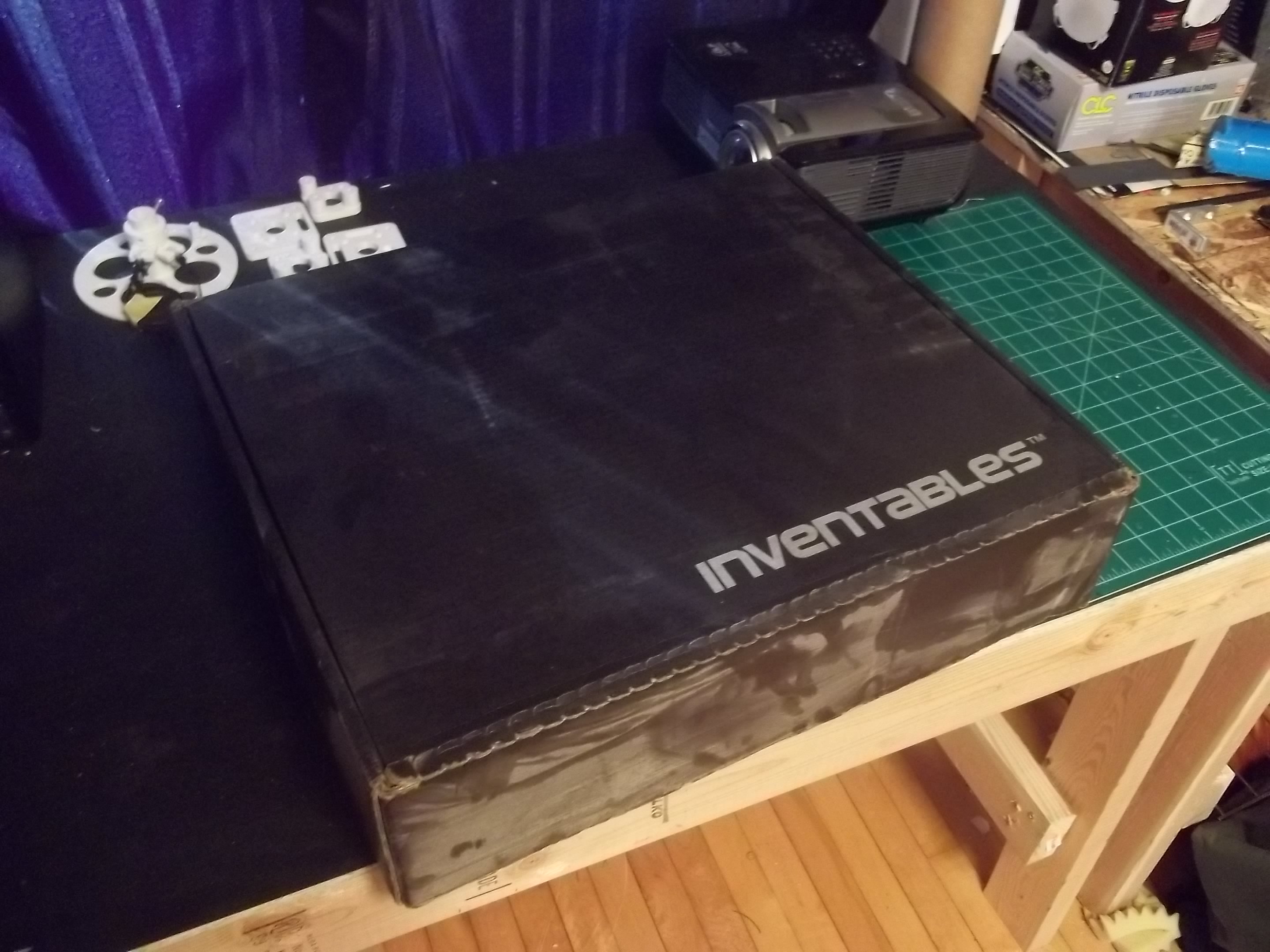
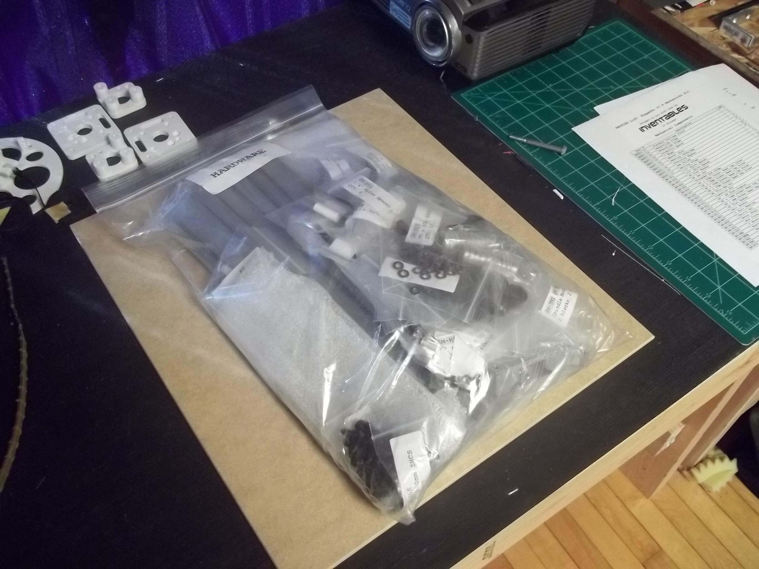
Unboxing the kit
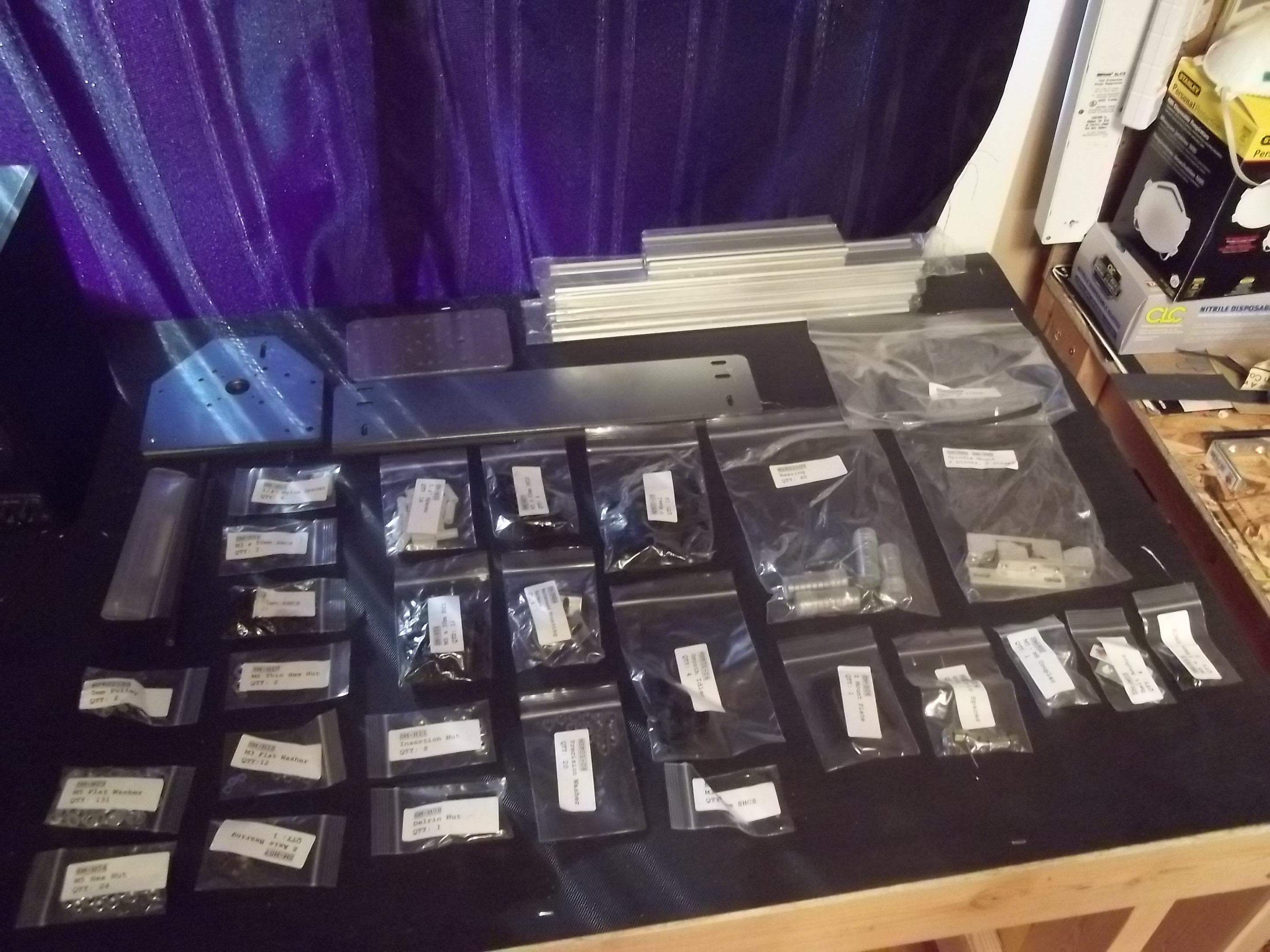
What arrived on my doorstep was a heavy black box with a big bag of bits and pieces sliding around inside. It could’ve used some better packaging, but hey, everything seems to be there. I do really like how all of the individual parts are bagged and labelled, so I spread it all out on a table to get a sense of what all I had.
Assembly of the mechanical kit
Overall, the assembly of the kit isn’t too bad at all. The creator of ShapeOko, Edward Ford, has provided a very useful assembly guide both in PDF form and as a wiki. There were only a couple of small problems, like not having quite enough washers, but nothing too major at all.
I picked up some pretty vanilla 68oz-in NEMA17 motors from Sparkfun and installed them on the appropriate plates, which is where a lot of my precious M3 washers went. During assembly, I found notes in the wiki stating that it is a good idea to put two extra M3 washers per bolt between the face of each stepper motor on the plate it’s mounted to, but the hardware kit did not include nearly enough washers for that (16 extra washers were needed). I had to run to a local hardware store to pick up the rest, and literally had dig out washers that had slipped under the container in the store to get enough. No hardware stores in my town have any decent stock of metric hardware :(
To install the aluminum linear rails correctly, you need to tap the ends yourself, which I found to be pretty annoying. I have a tap and die set, but only a cheap $20 one from my local hardware store. My T-handle kept slipping around the tap, and I had too much friction to thread it by hand. I ended up using a hand drill, but the load took a toll on my batteries and was probably the most labor intensive part of the build.
[flickr-gallery mode=”photoset” photoset=”72157631915062186″]
Testing the main frame and gantry motion
After the main frame and gantry were assembled, I had to adjust some bits to get the motion to be nice and smooth. My X/Z axis (the part mounted to the moving gantry) moves very smoothly and didn’t really require much fussing. My Y axis was, and still is, a bit more difficult to move and is slightly jerky. I’ve tried adjusting the eccentric screws three or four times already and get the same result – either one or more the V-wheels spin too freely, or the overall gantry motion starts to stick. Hopefully it is good enough right now that my steppers can do their job.
Next steps
Now that my mechanical frame is pretty much set up, the next thing to do is to source some electronics and a spindle. Honestly this part of the process is a little stressful, because I don’t want to spend good money on something that is not quite right for me. Right now, it seems like the control electronics are pretty obvious – a GRBL-compatible shield with stepper motor drivers and an Arduino Uno. It’s the spindle I’m not completely sure about right now.
I’m leaning towards getting the DeWalt DW660, but I am concerned about how to mount it to my Z axis. I also hear it is quite loud, but it seems to me that its going to be loud no matter what when material is being carved.
Once I’ve got the electronics and spindle involved, a couple of basic “hello world” tests will be needed for me to get familiar with the workflow. Hopefully before too long I’ll making some actually creative projects! I’m extremely interested in creating works from generative algorithms and morphogenic processes. If I can explore some of the more esoteric computer science topics like genetic algorithms, cellular automata, neural nets and chaos simulations I’ll be one happy maker!