Giant Lite Brite for KANEKO
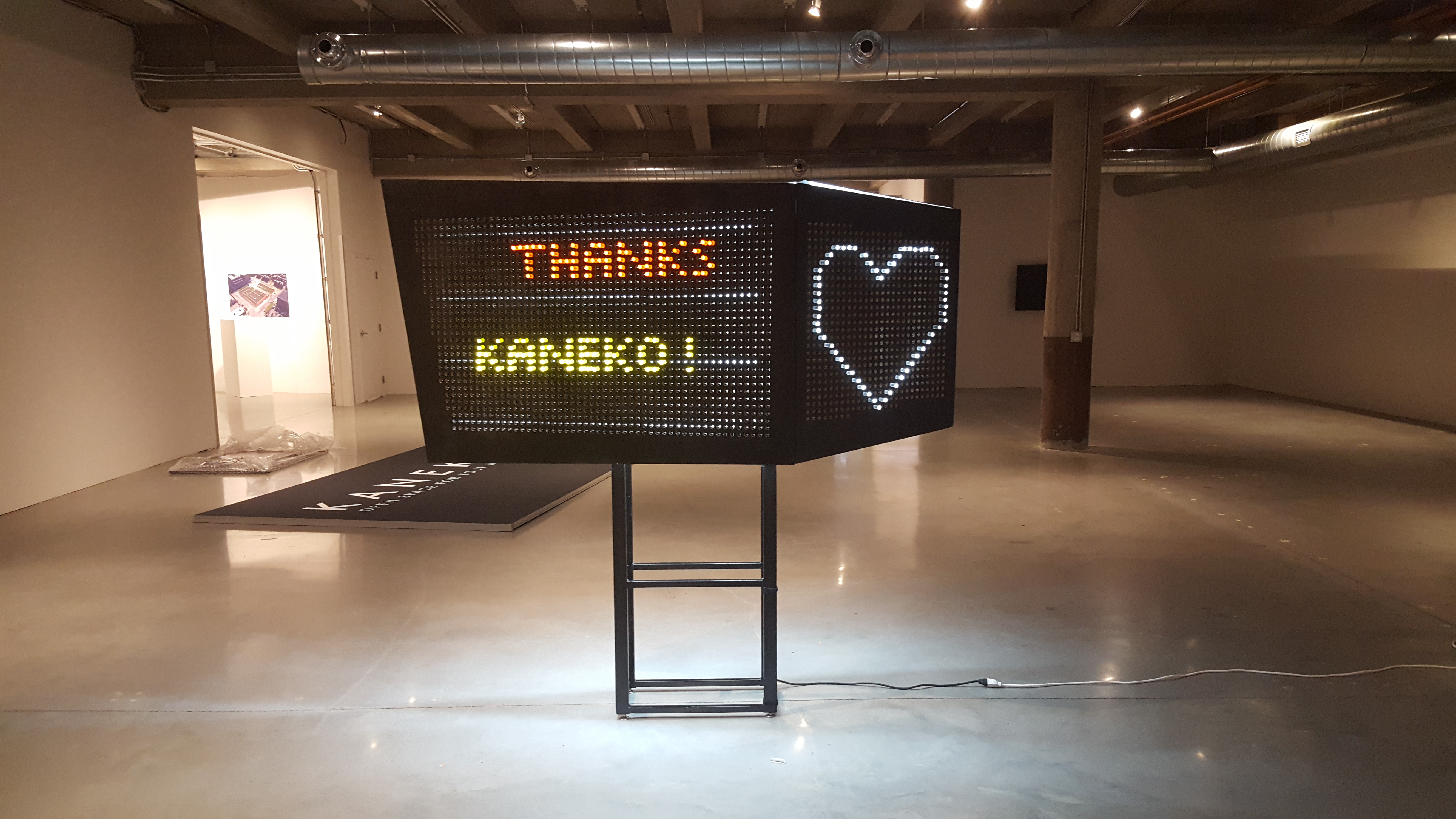
![]() In the fall of 2017 I was granted the opportunity to design and build a massive, interactive, three-dimensional version of the classic “Lite Brite” children’s toy for a seasonal exhibition titled light at KANEKO in Omaha, NE.
In the fall of 2017 I was granted the opportunity to design and build a massive, interactive, three-dimensional version of the classic “Lite Brite” children’s toy for a seasonal exhibition titled light at KANEKO in Omaha, NE.
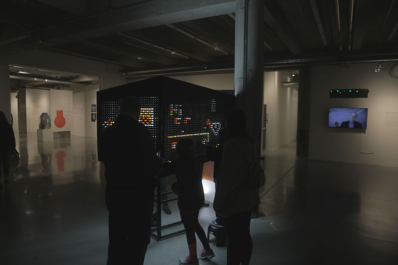
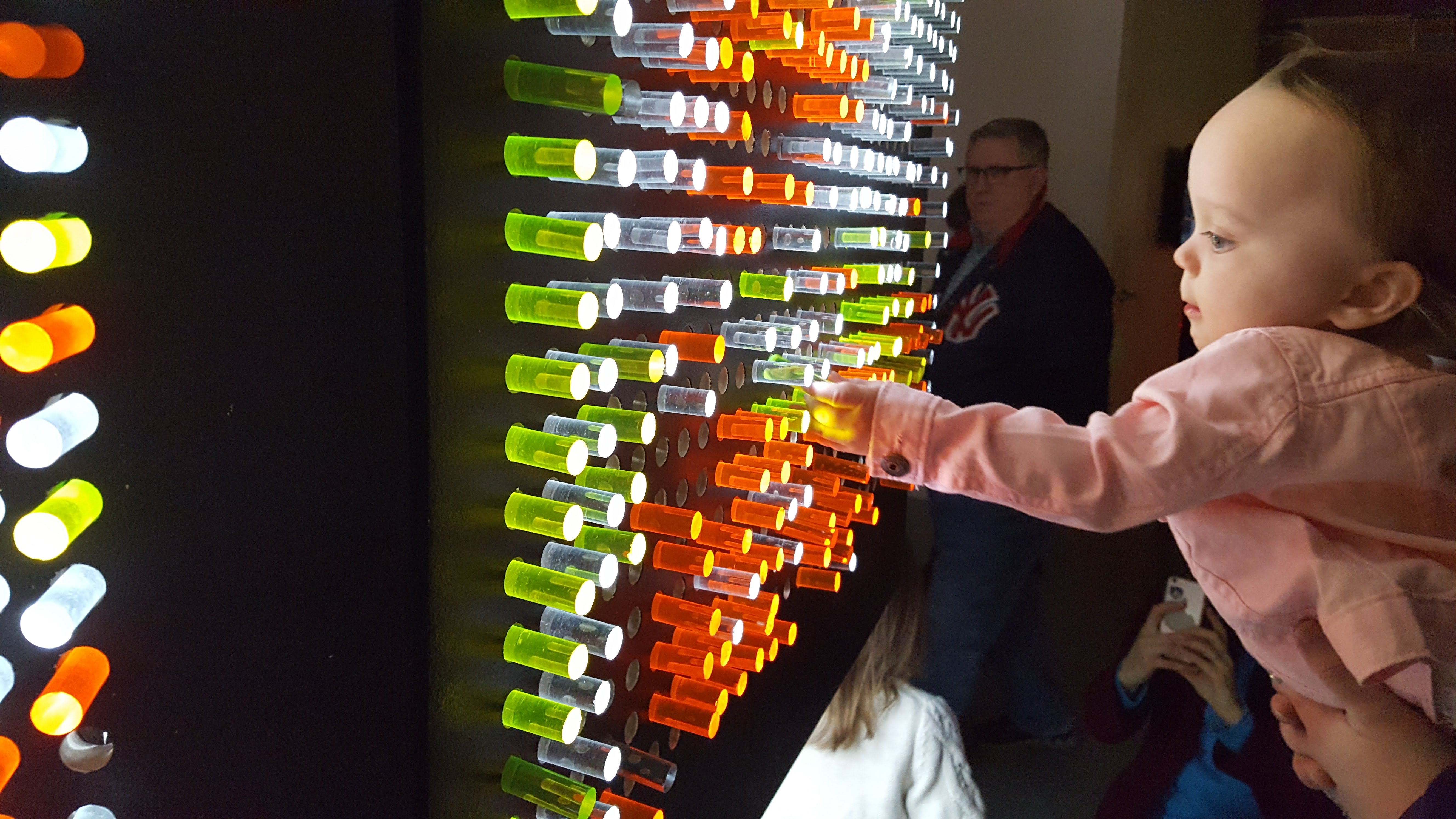
The exhibition was attended by the largest crowd sizes KANEKO has ever recorded, with the Lite Brite seeing a near-constant stream of visitors every day throughout the three-month run. Not only did this piece survive the exhibition, but it did so without needing a single day of downtime or needing any major maintenance! Even better, after the conclusion of the show the piece was donated to the Autism Center of Nebraska where it will be enjoyed for a long time to come.
This project was a very welcome challenge that required my attention nearly every evening and weekend over the course of three months (I still work full-time as a UI developer, after all!). Throughout the build process I was able to apply familiar skills in CAD, CNC routing, laser cutting, and 3D printing, and pick up some new ones like MIG welding and metalworking. Any project where I get to learn something new is a win in my book!
Special thanks to the staff of KANEKO for the opportunity, and to Ben Semisch and Hari Wiguna for various photos and videos of the finished piece.

Build log
Concept
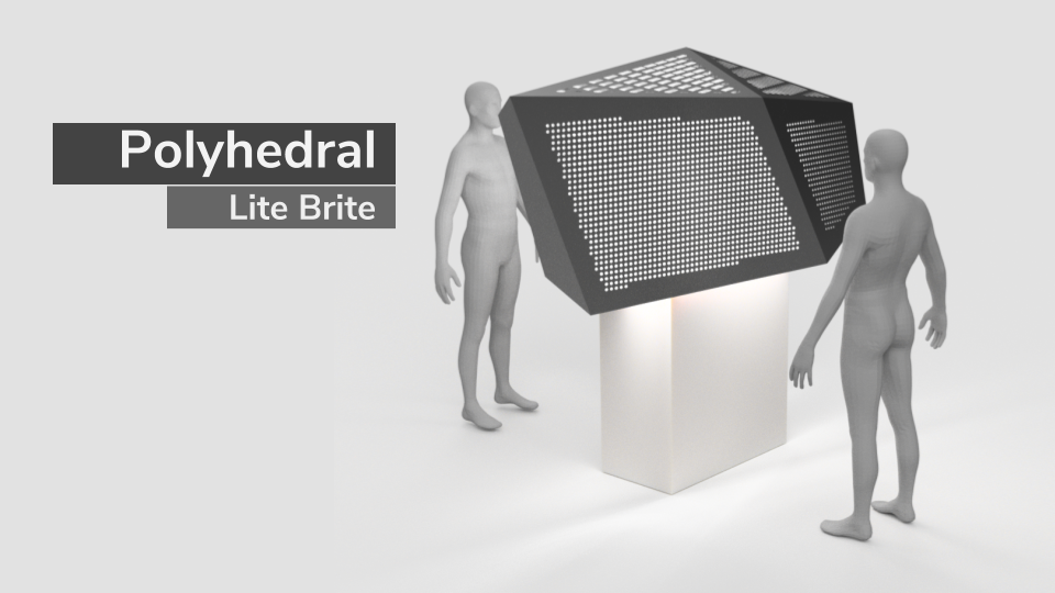
KANEKO had a clear and simple request for this project – build a scaled-up version of the classic children’s toy Lite Brite that people of all ages could interact with over the period of three months. After some sketching and prototyping, I knew I wanted to make something big, three-dimensional, and somewhat abstract. I wanted to make something that was striking in it’s appearance, yet ultimately highlights the patterns of illuminated pegs that visitors would create without detracting from them.
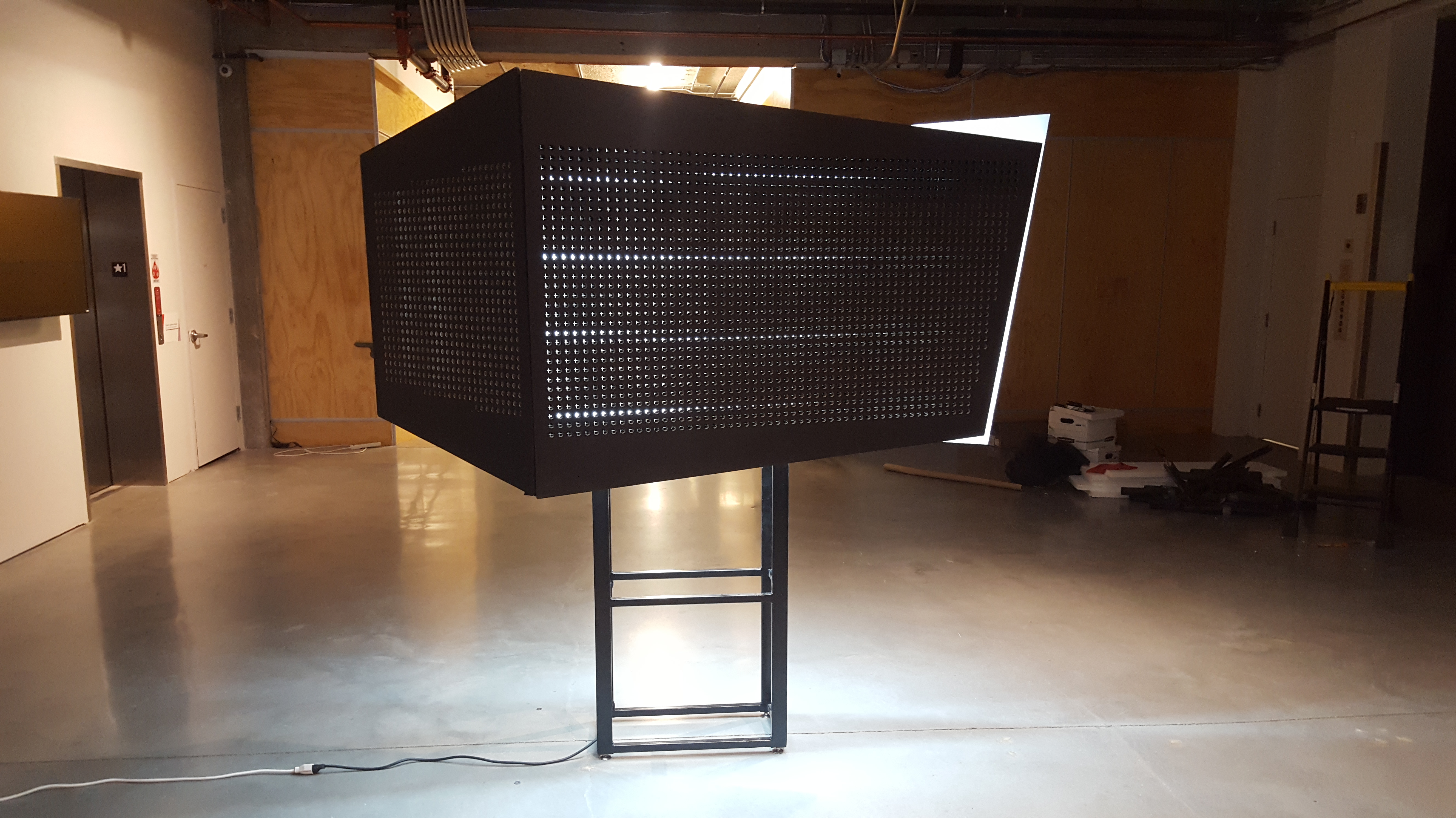
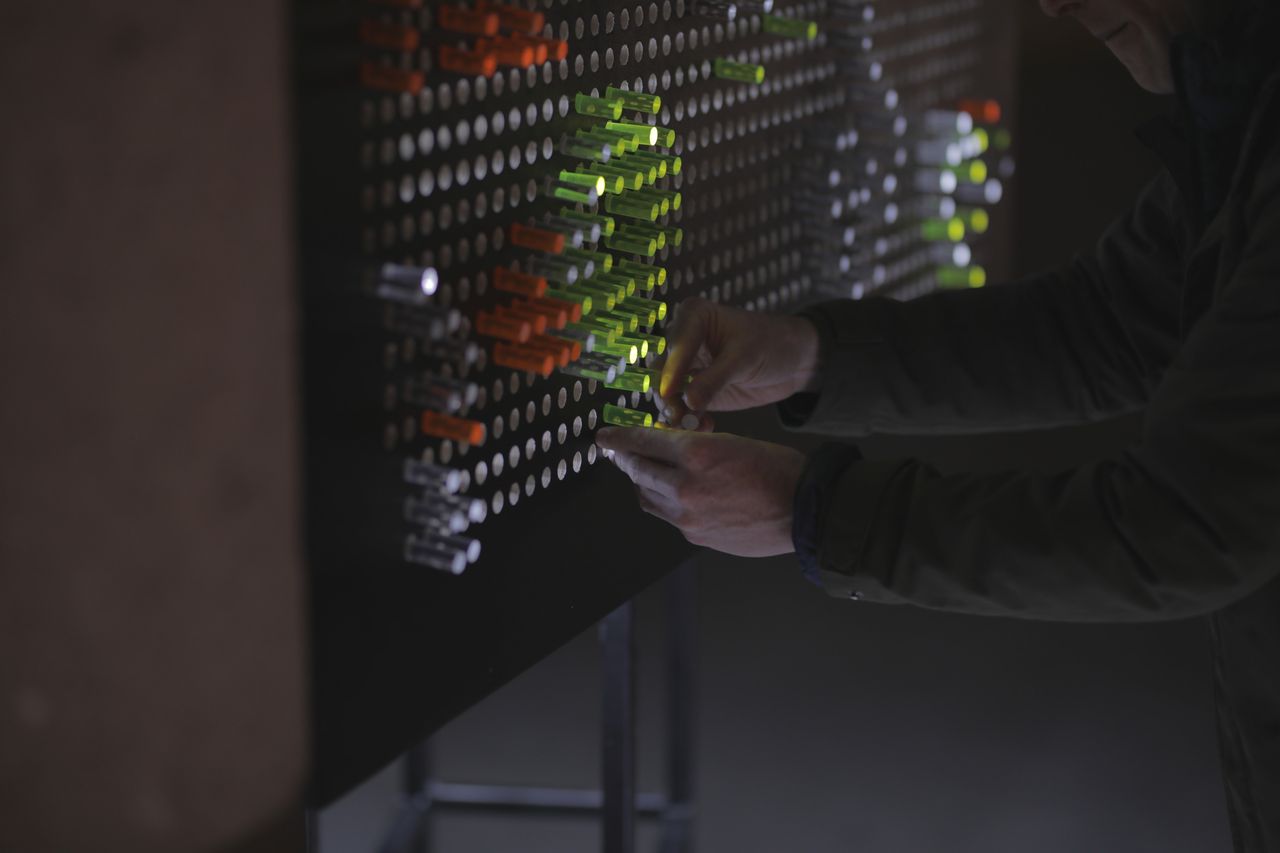
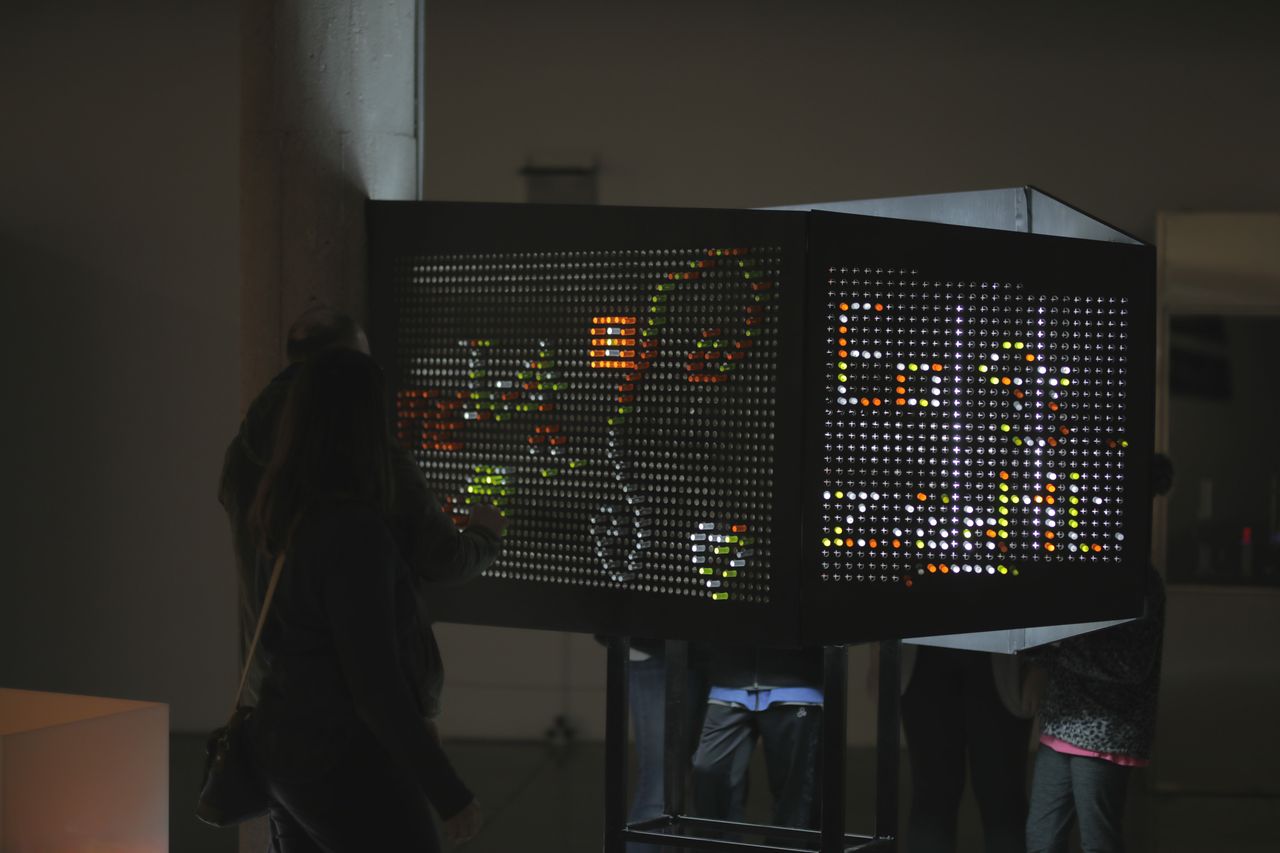
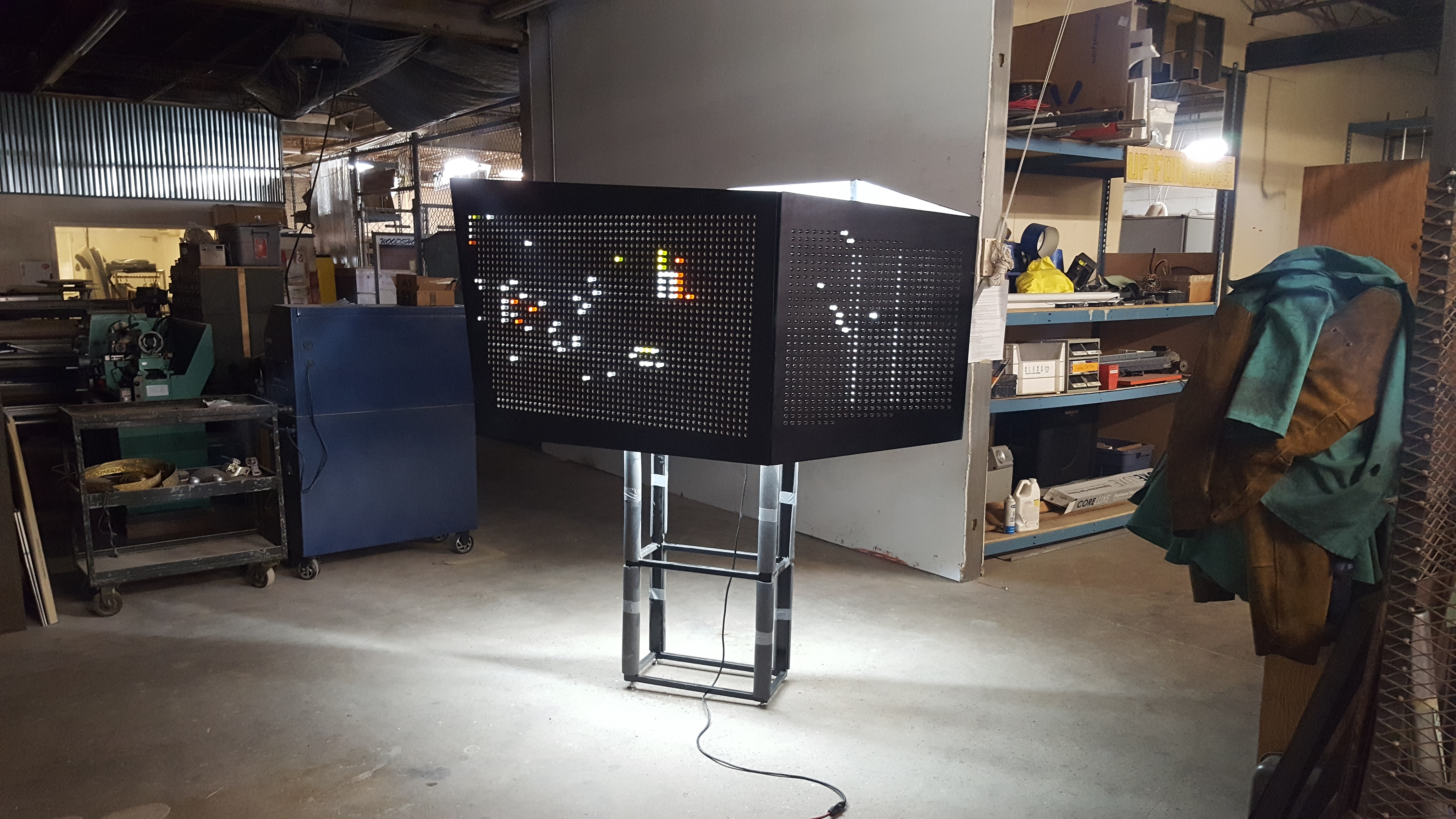
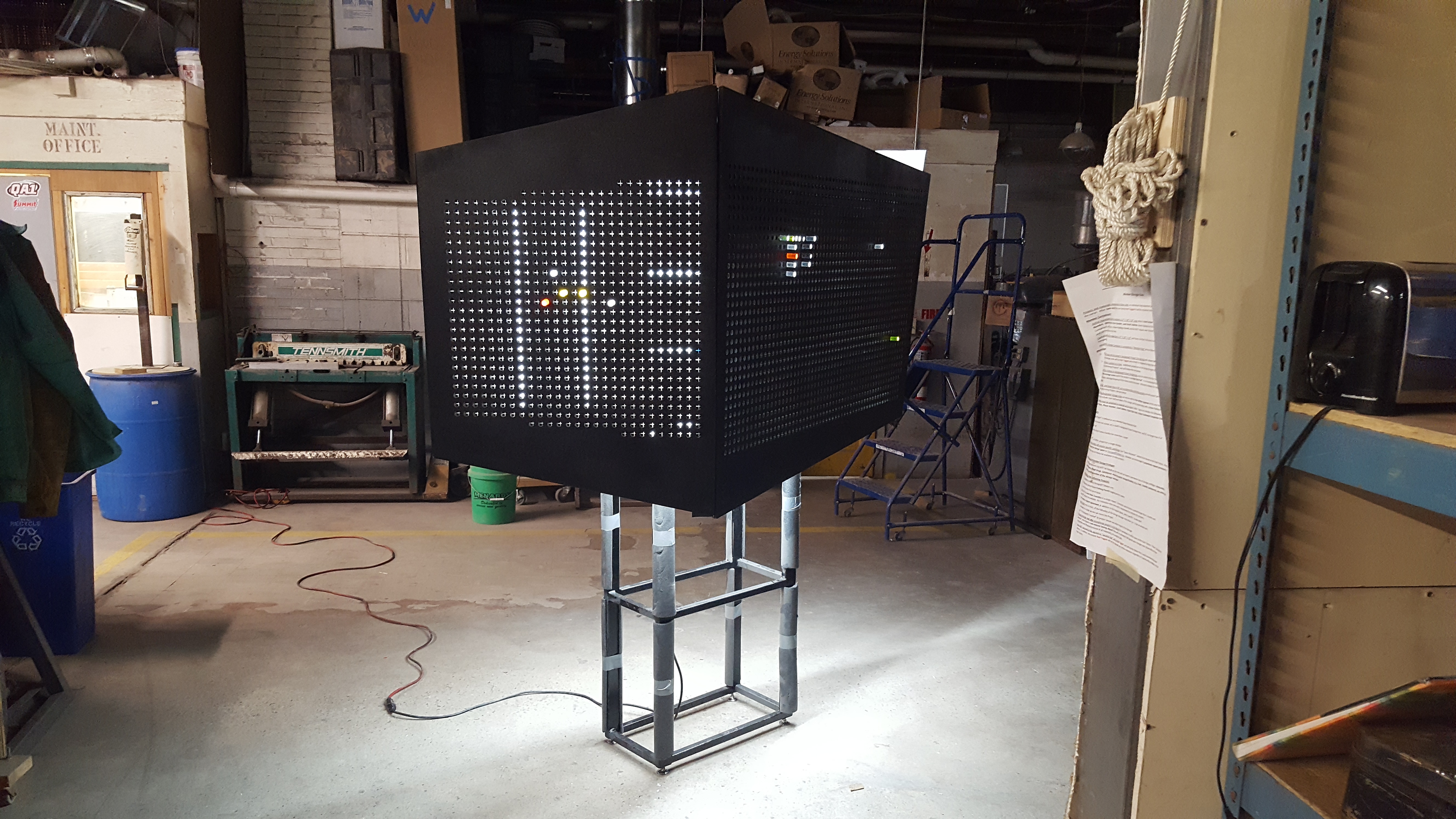
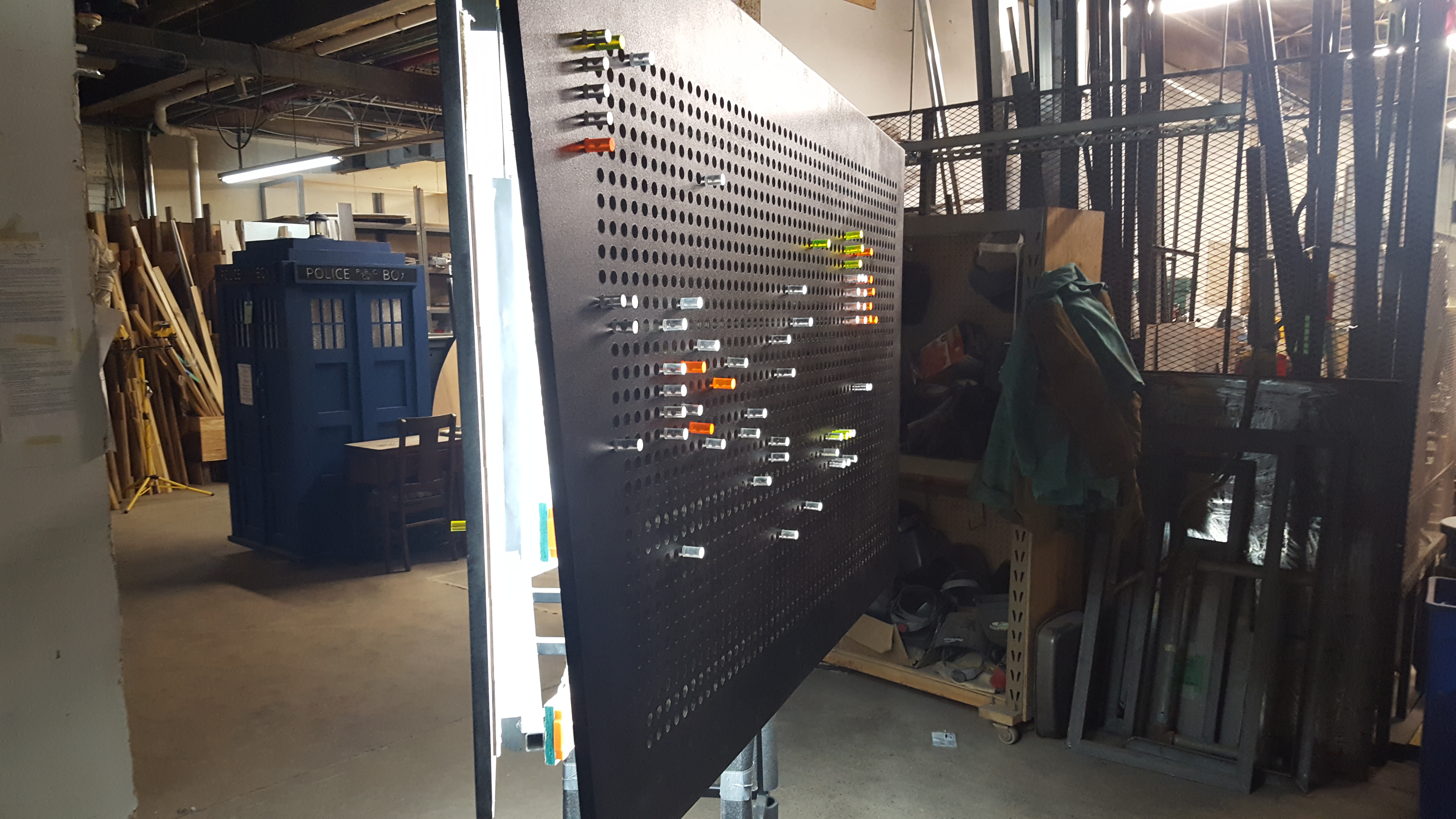
What I came up with was a large, freestanding structure comprised of four distinct “faces” with thousands of holes drilled into them to accommodate complex designs from multiple visitors at a time. Visitors could approach the piece from any angle and use custom-made acrylic pegs to build designs much like pixels on a digital screen. All of these pegs would suddenly burst with light as they are inserted into the piece through specially-crafted self-healing rubber baffles, creating the sensation that these simple acrylic rods were little cylindrical light bulbs that would only turn on when inserted.
To communicate my concept I put together a proposal presentation for KANEKO with three-dimensional renders along with a piece-by-piece breakdown of the various sub-assemblies of the piece and their associated cost and labor estimates.
To give credit where credit is due, valuable insight for this project was gleaned from Noah Weinstein’s 2008 Giant Lite Brite project, which he graciously documented over on Instructables. His notes about materials, construction methods, and what he would do differently were of great help to me as I was planning this project out, and saved me a good amount of time in prototyping. Thanks Noah – I owe you a coffee!

Design and planning
Once the concept had been proposed and approved, the very first thing to do was to model the entire piece in CAD in order to make key decisions about materials, geometry, fabrication and construction methods, and more. For this I used Autodesk’s Fusion 360, which I had some positive experiences with on smaller scale projects, and this decision turned out to be one of the best choices I made throughout the entire project.
Not only could I model every aspect of the piece digitally with this tool, but I could also ended up leveraging it’s analysis tools and rendering, animation, and CAM capabilities to research, prototype, fabricate and share my thought processes and designs with the client and various vendors and job shops throughout the project. The flexibility, capabilities, usability, documentation, and low learning curve of Fusion 360 all surpassed my expectations by a long shot, and now I strongly recommend Fusion 360 to anyone looking to design parts for fabrication rather than the smattering of “kinda sorta good” open-source options I used to use.
Polyhedral shell
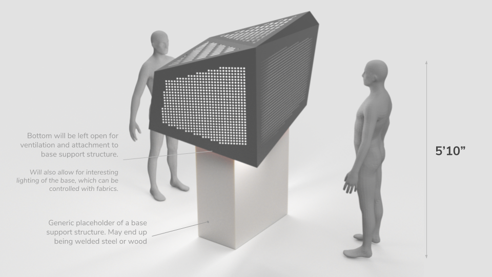
The starting point for this piece was the design of the outer “shell” made of plywood panels with holes that visitors could interact with by inserting colored acrylic pegs. Based on some low-tech prototyping and discussions with the client I knew early on that I wanted the overall footprint of this shell to be about 4ft wide, 8ft long, and about 4ft tall. These dimensions would also ensure that I could fabricate each individual “face” of the shell using standard 4×8′ plywood sheets without having to split them up and end up with an unseemly gap or line splitting them up strangely.
Using Fusion 360’s 3D Sketch feature I played around for some time with different geometries, eventually settling on one with slightly straighter edges than what was shown in my original concept renders so that more holes could be fit into each face, enabling larger and more complex designs from visitors. Special care had to be taken to keep all four of the main panels as vertical as possible while still maintaining an overall feeling of asymmetry and visual interest.
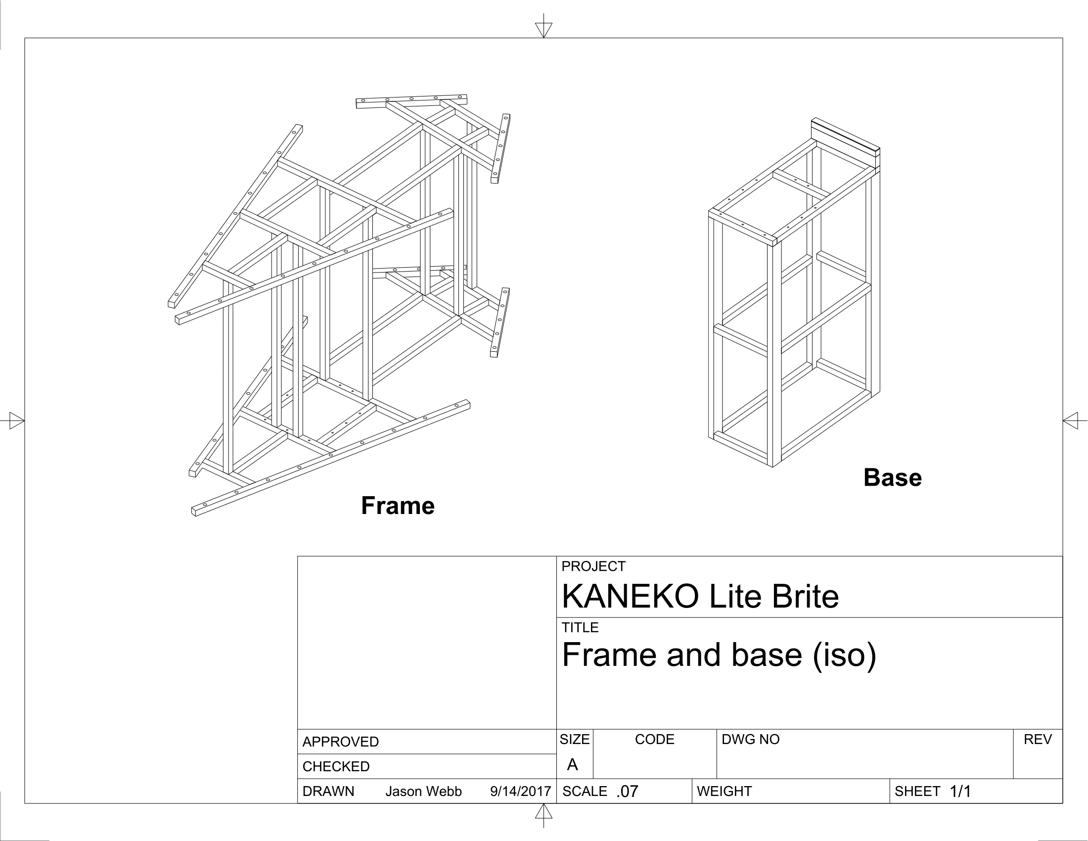
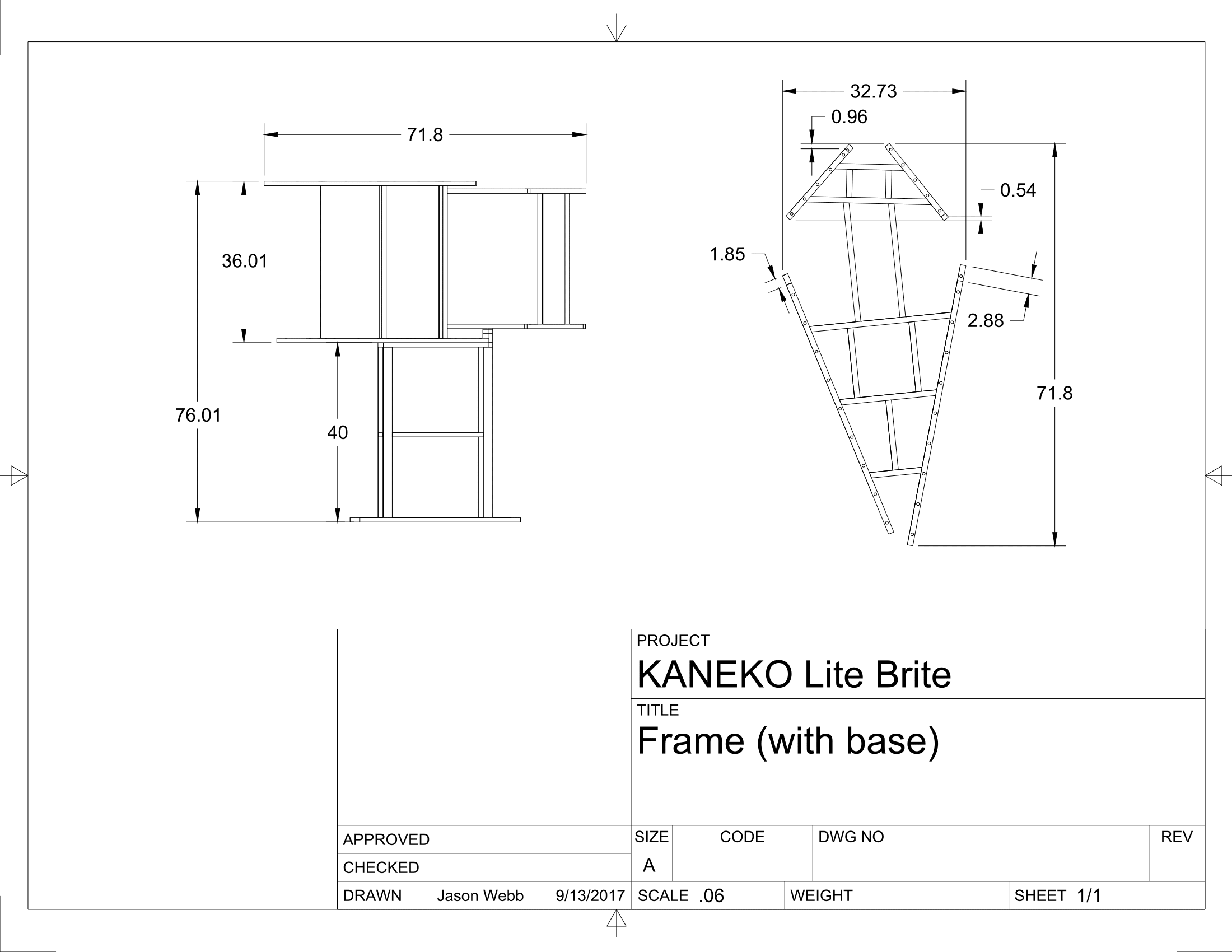
Frame and base
Based on this irregular, three-dimensional polyhedral shape I then designed an internal frame structure to support each of the outer panels, to be fabricated using 1″ square steel tubing.
The plywood panels would be fitted with custom angle iron brackets with holes paired with matching holes drilled into the angled rails of the frame itself such that panels could be securely hung and fastened to the structure easily.
The frame was inset from the polyhedral shell by the thickness of the plywood panels such that it would be entirely hidden as the shell is constructed, requiring the panels themselves to have mitered edges so they could fit together perfectly.
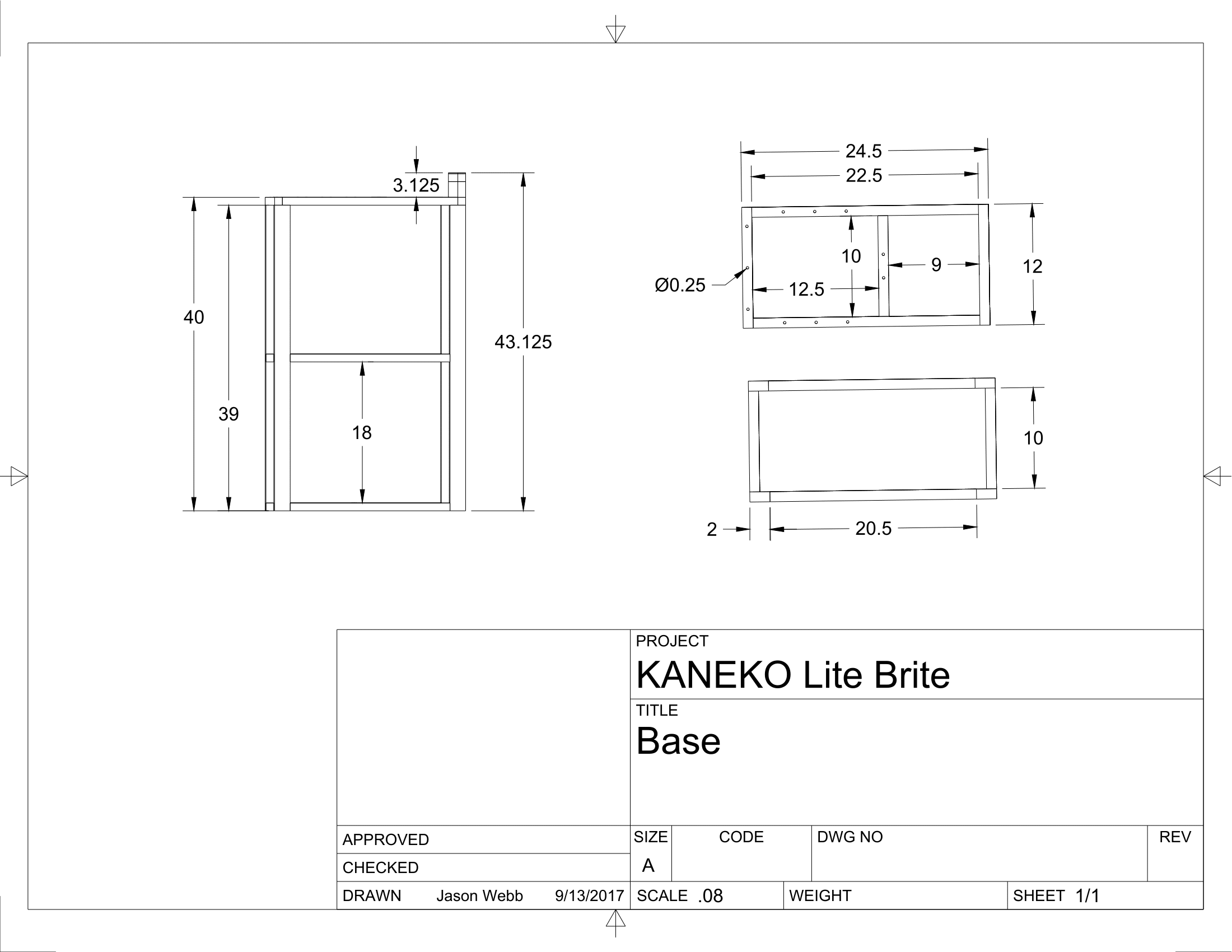
A steel base (made using both 1″ and 1×2″ steel tubing) was also designed to securely support the frame at key points based on the center of mass identified by Fusion 360.
About 72 feet of steel tubing was used in the making of the frame and base, weighing just over 100 pounds (45kg)
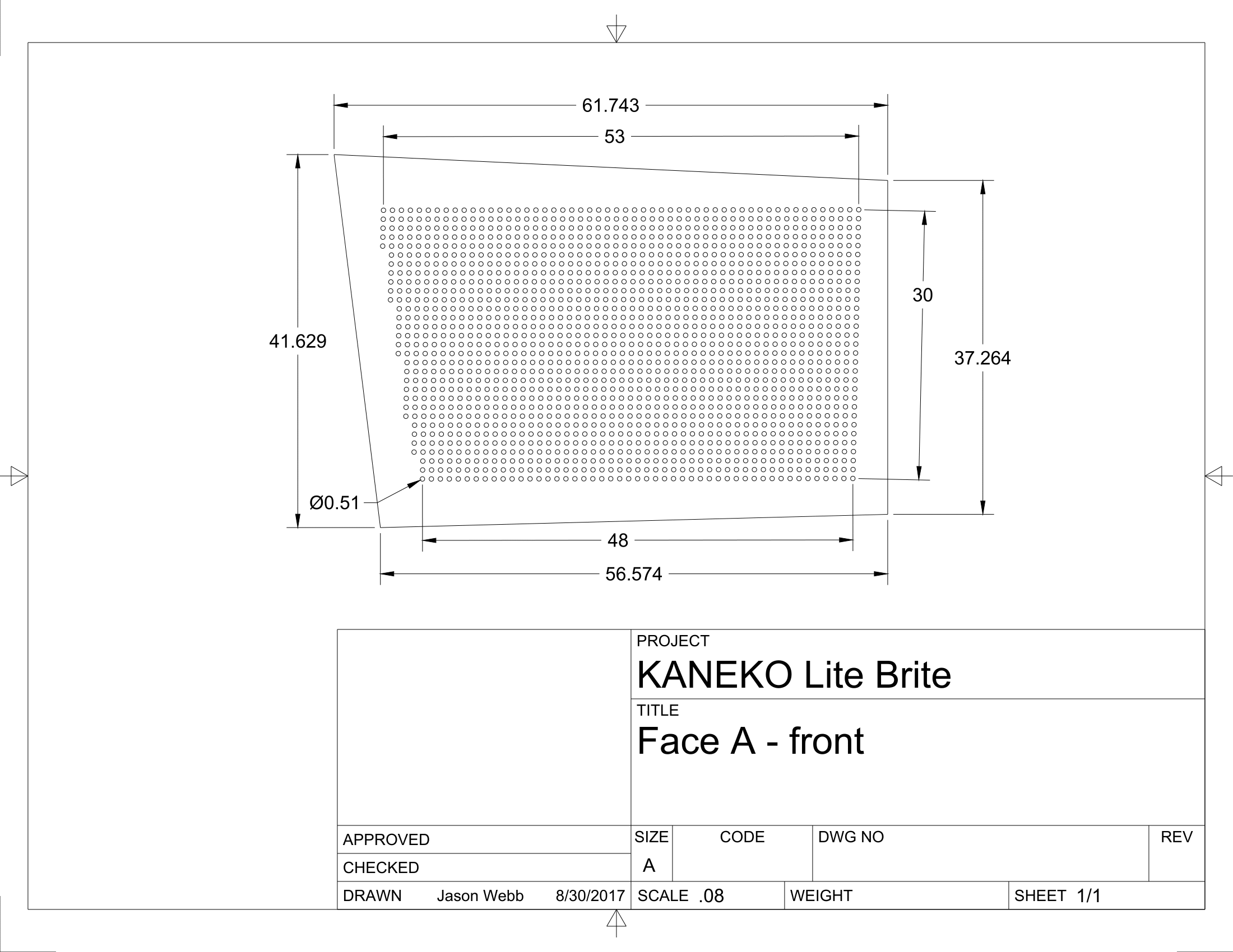
Panels
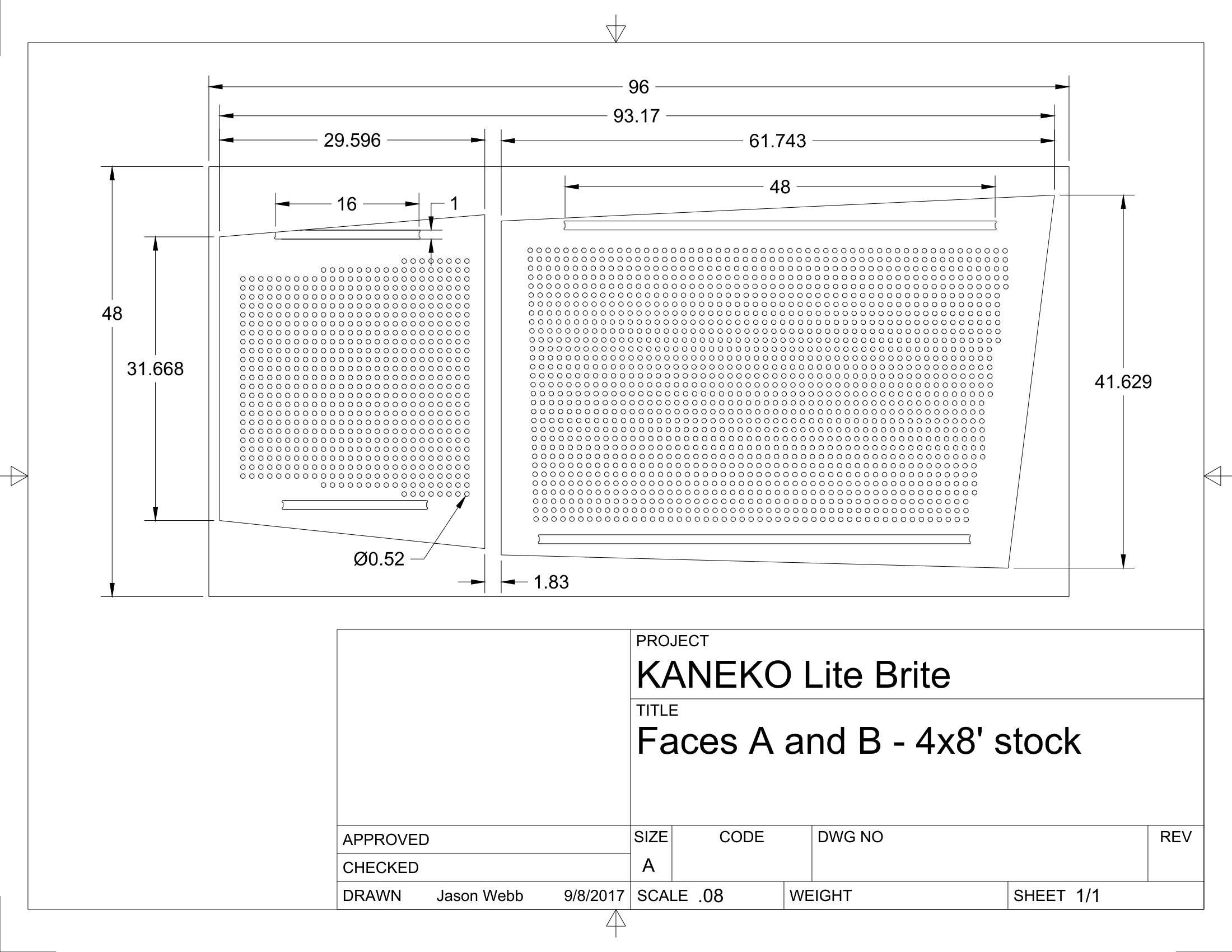
Each of the four main faces of the polyhedral form needed to have as many holes as possible in them without compromising the integrity of the material itself. Based on small-scale prototyping, I felt that using a pitch (the amount of space between holes) of one inch would be provide a good balance of good material strength and density of pegs with a hole diameter of just over 1/2″.
Creating the hole pattern designs for each panel in Fusion 360 really pushed my laptop to it’s absolute limits, and made me wish I had sprung for a more powerful CPU. If there is anything I could complain about with Fusion 360 it would be it’s over-reliance on the CPU rather than the GPU for the computations of very large patterns. At least at the time of this writing it sounds like Fusion 360 is only using the GPU for basic on-screen rendering and not tapping into the raw computing power of the GPU, which for my project manifested itself as a serious productivity bottleneck. I often had to wait between 5-10 minutes when doing edits to my hole patterns, which really gets tedious fast!
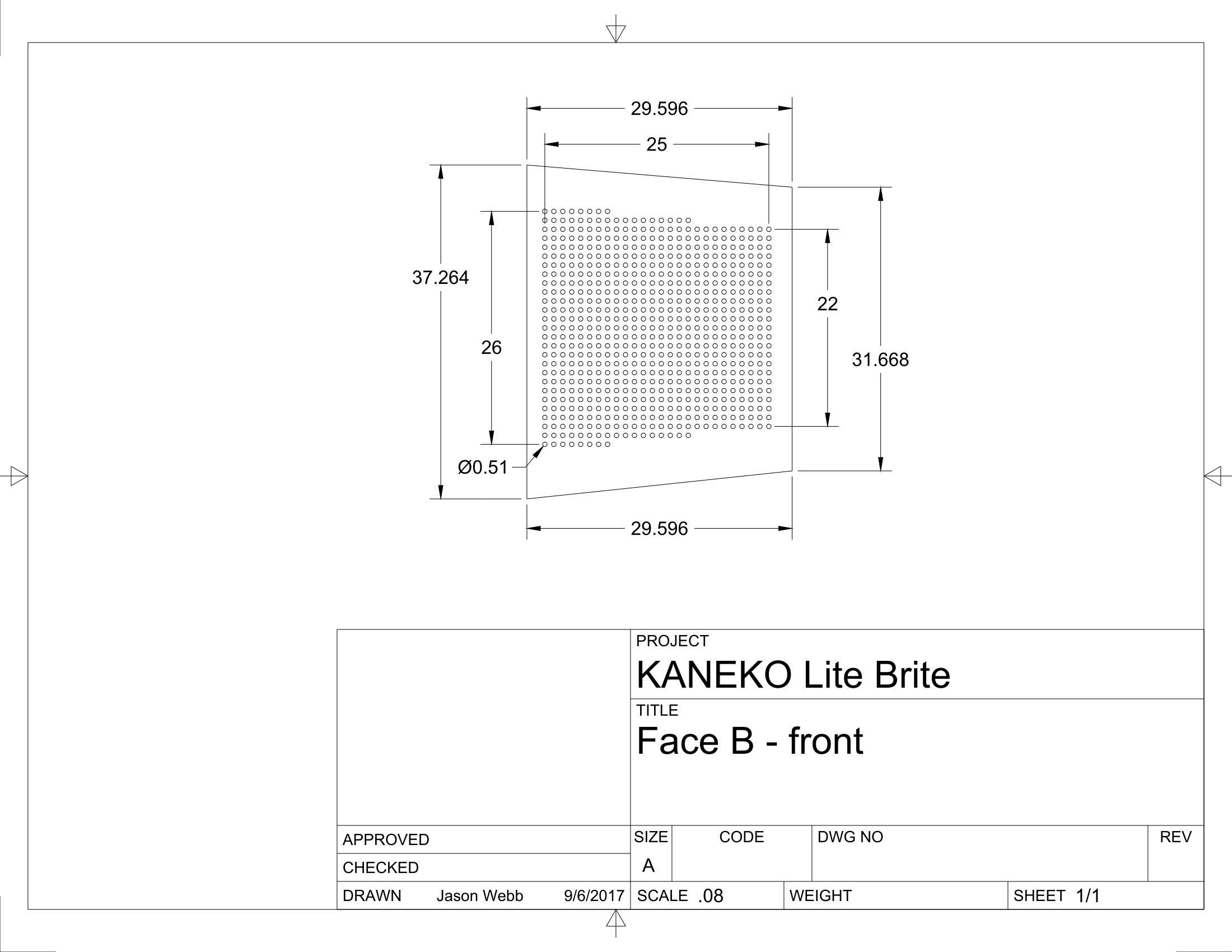
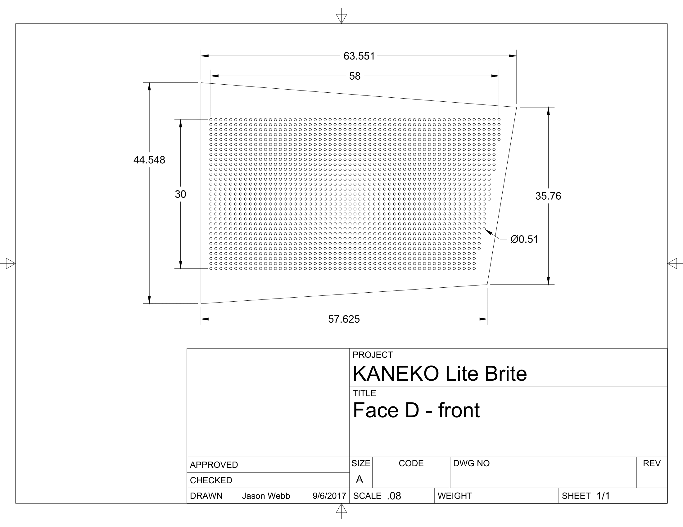
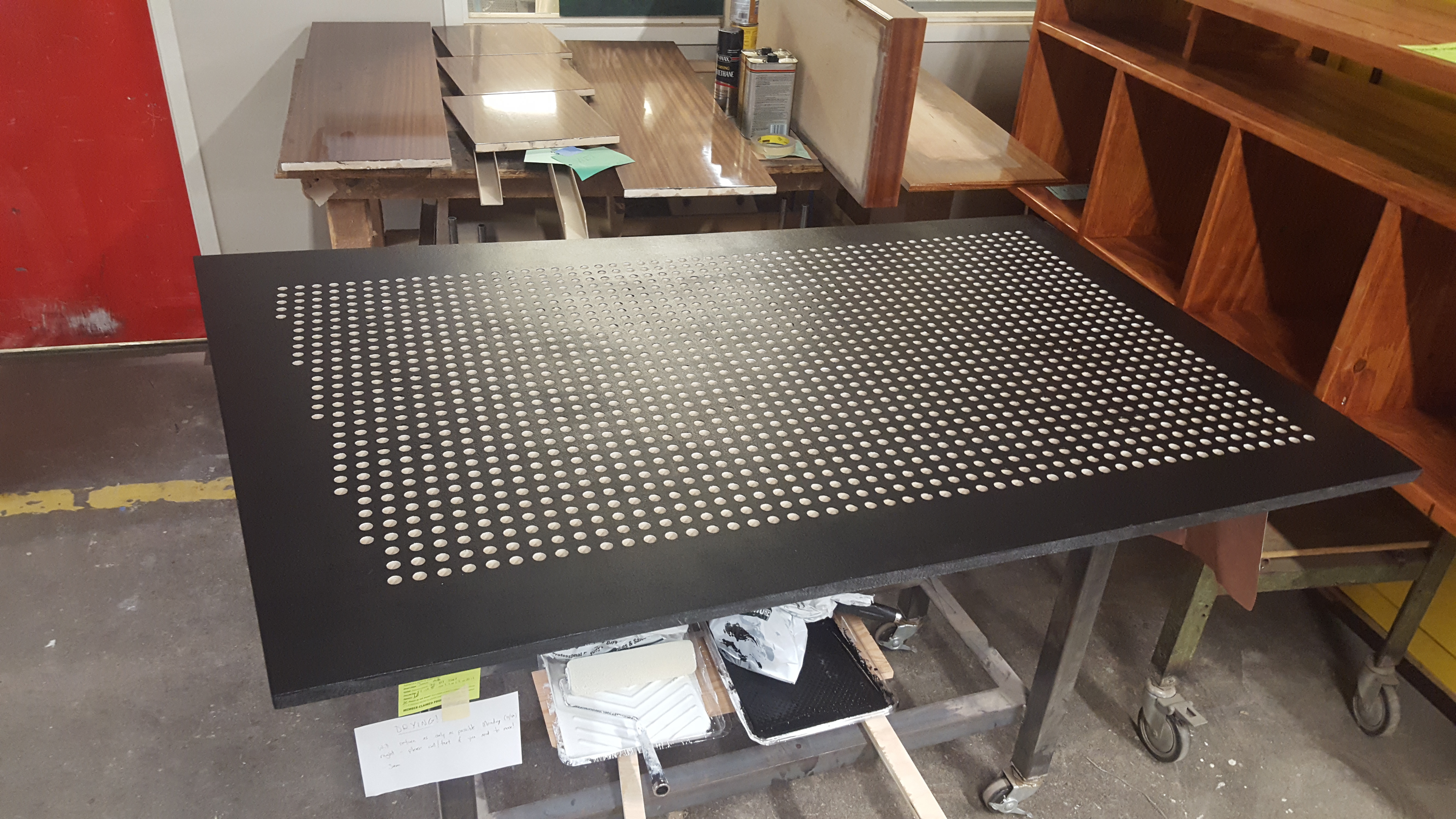
Each of the larger panels would end up measuring about 5ft wide by 3.5ft tall with around 1,650 holes.
Each of the smaller panels would be about 2.5ft wide by 2.5ft tall with around 650 holes.
All of the panels could be routed out of just two sheets of 4×8′ x 3/4″ plywood and would end up with over 4,600 holes for pegs!

Light baffles
 Wooden panels with holes in them would not be enough, though, because there needed to be some sort of physical barrier to prevent pegs from being pushed too far in and falling through, and to prevent light from inside the piece from escaping even when pegs are not inserted.
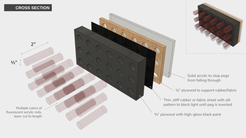
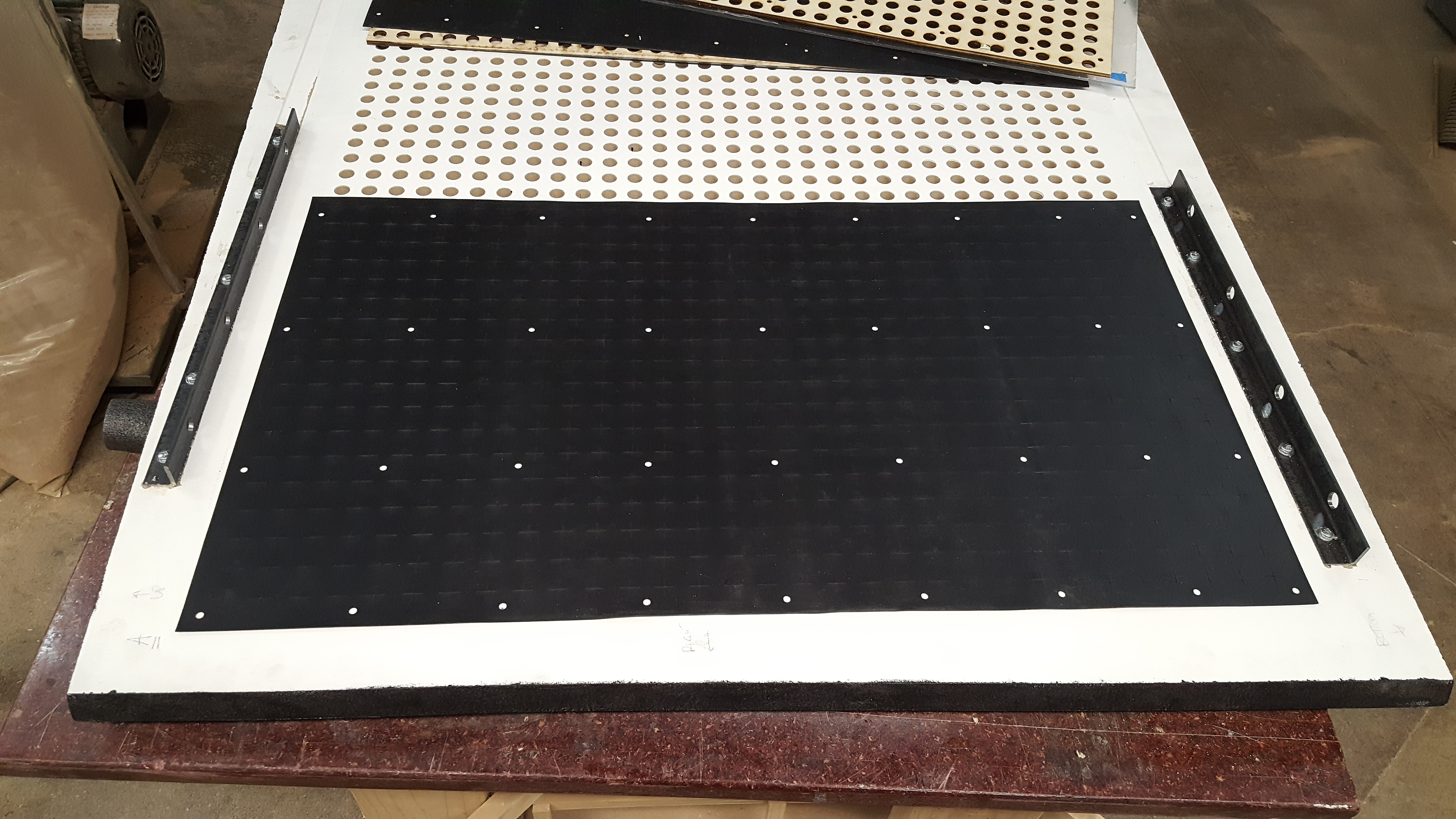
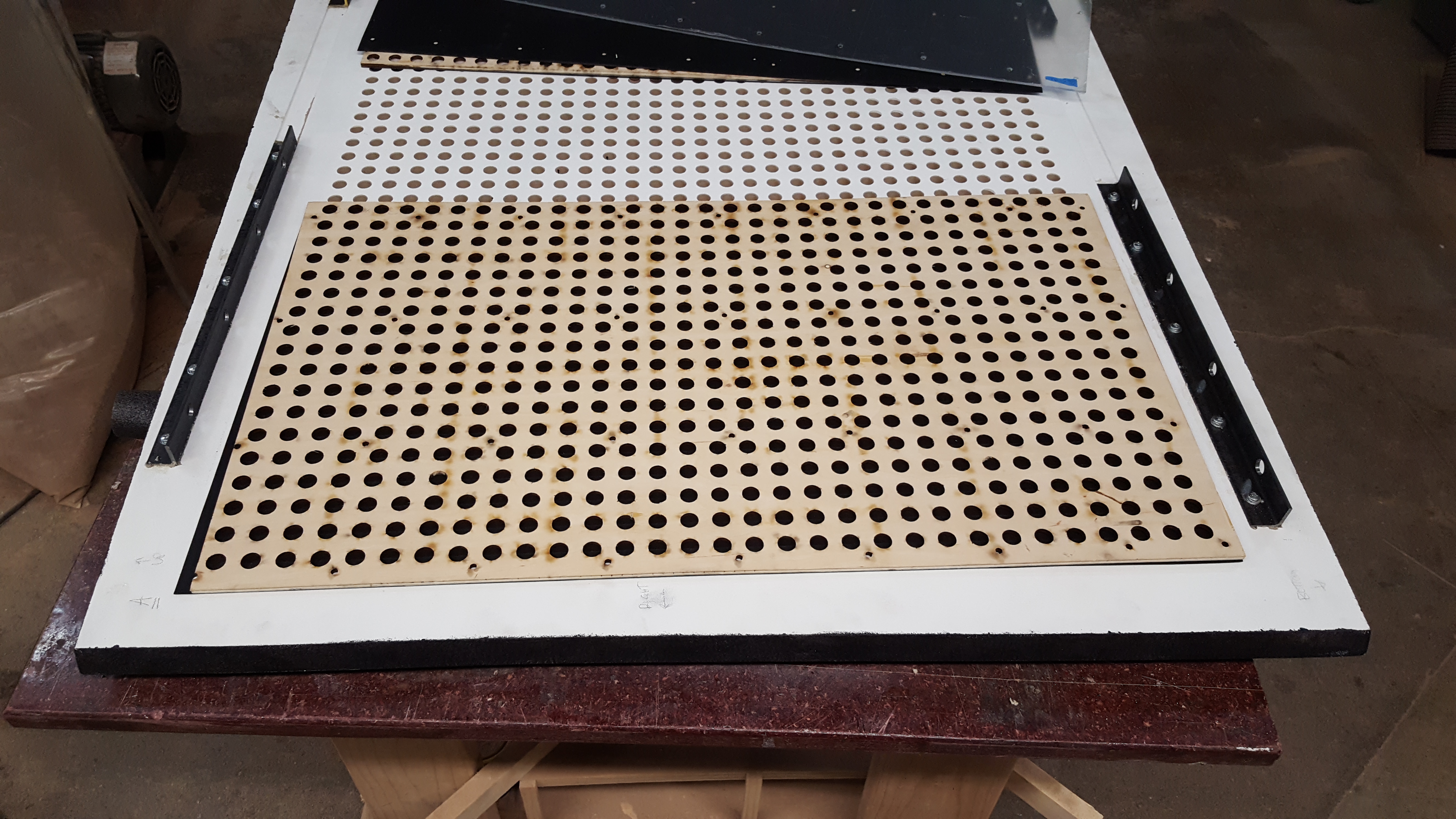
Expanding upon the technique used in Noah Weinstein’s Giant Lite Brite, I designed a “baffle” system that uses thin plywood, special “laser safe” rubber sheets, and plexiglass to be semi-permanently attached to the back of each panel. Short wood screws would be used to fasten the entire stack of materials to the outer panel itself for maximum strength and rigidity.
To block light as well as provide a good grip on the pegs, thousands of tiny “+” signs would be laser-cut into the rubber sheets to create four “flaps” per hole that would spread apart when a peg is inserted, then spring back when it is removed. After experimenting with a handful of different types of rubber, I found that the type of rubber used by Noah in his Lite Brite (called Santoprene) had the best balance of low-odor, low-smoke, cut quality, rigidity, and cost per square foot for this application.
Behind the rubber sheets would be a layer of thin plywood with the same laser-cut hole pattern as the outer panel, but with a slightly larger diameter to allow the Santoprene rubber flaps to open fully without obstructing the pegs’ travel, though still maintain a grip on them to firmly hold them in place.
Finally, a solid layer of plexiglass would be installed directly onto the plywood layer to provide a stopping point for each peg while allowing for light to be transmitted fully into them.
Pegs
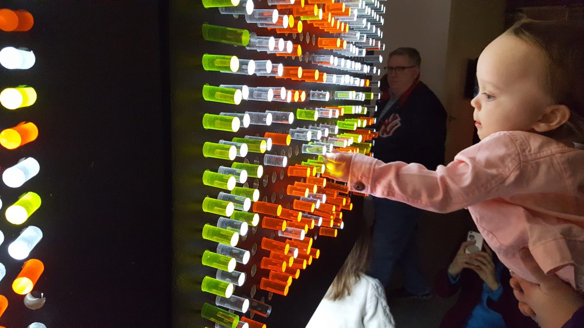
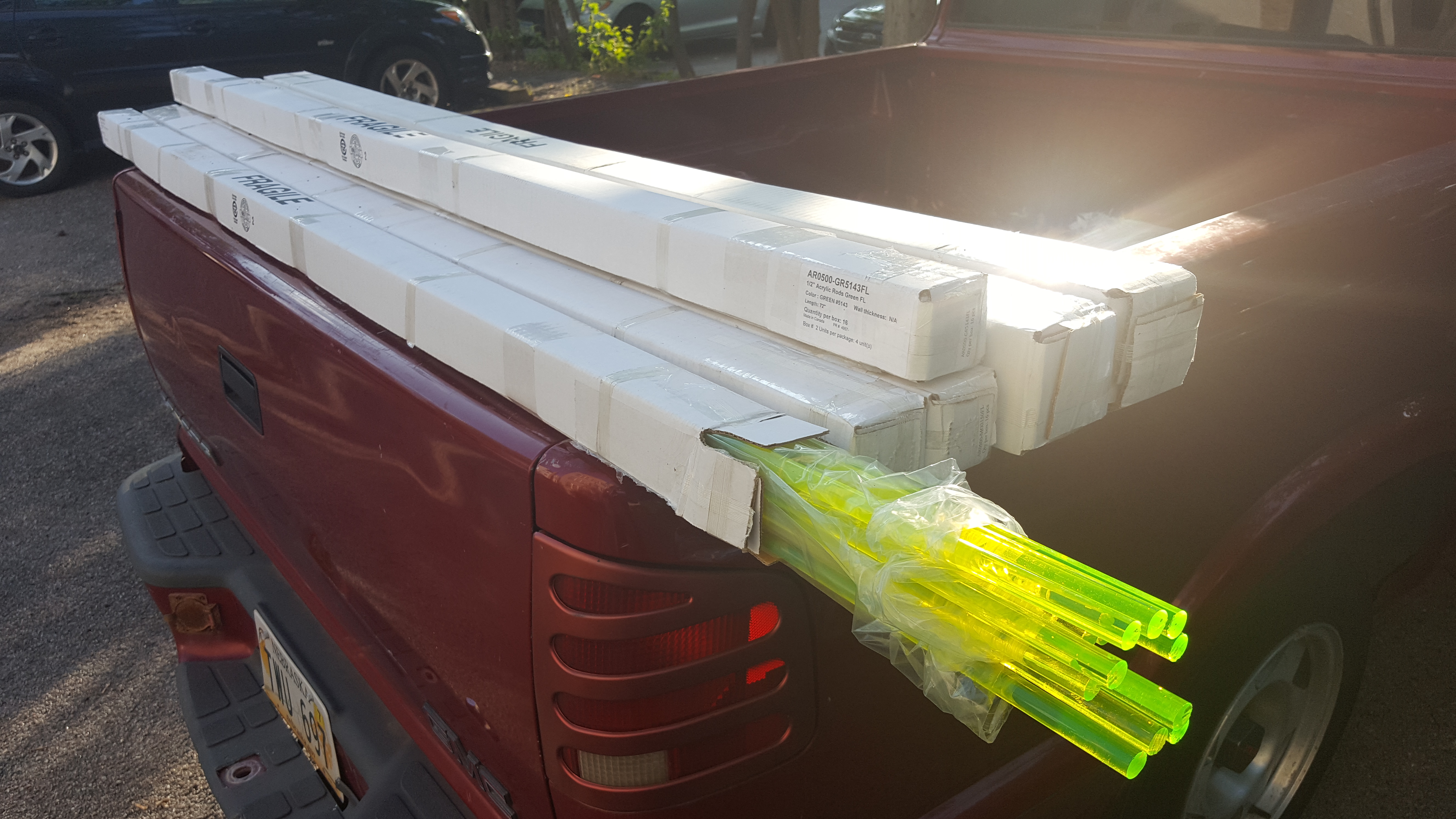
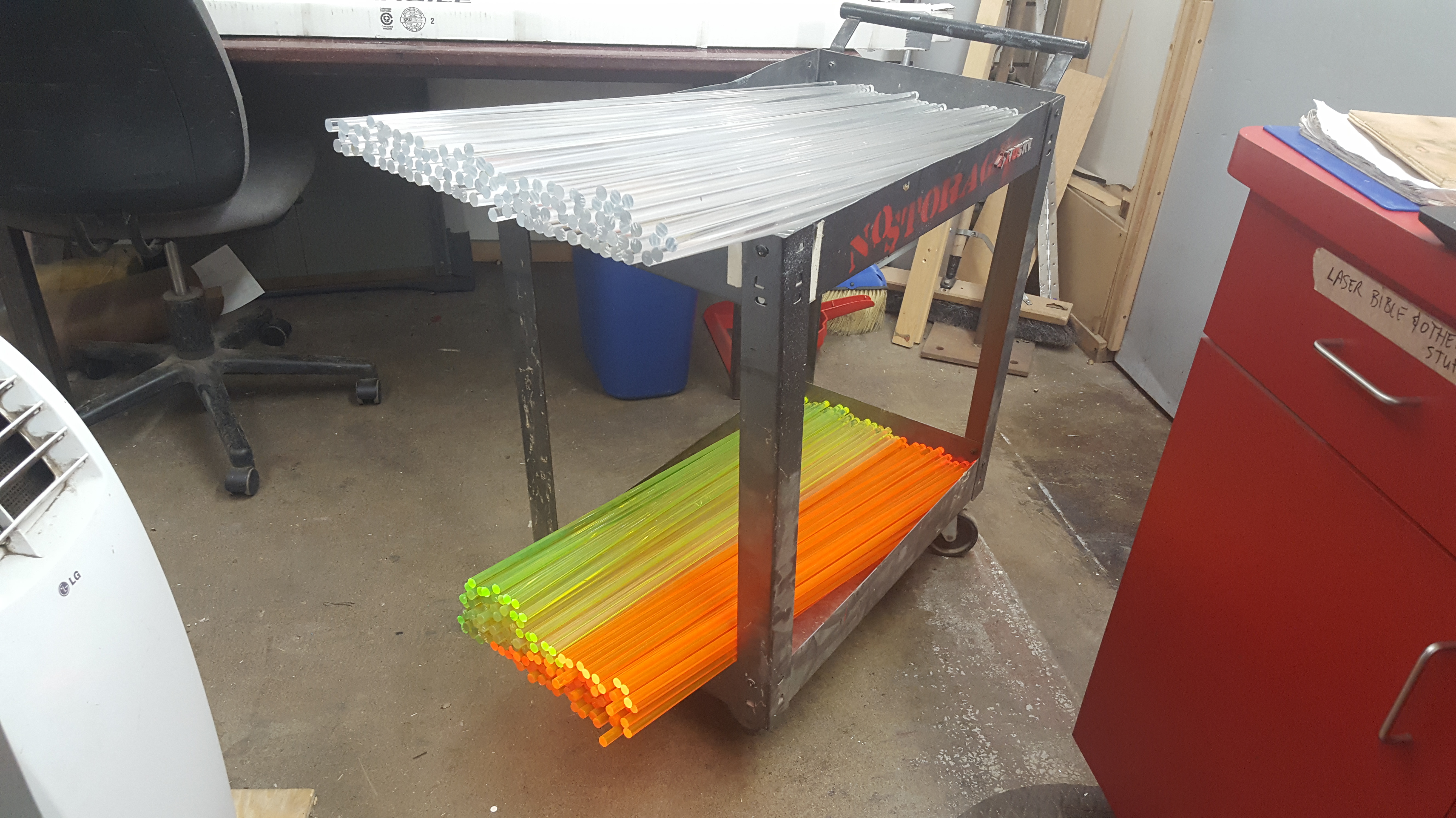
 Finally, no Lite Brite is complete with brightly colored translucent plastic pegs that can be inserted and removed to create patterns on the panels. For this project I used acrylic rods in two beautiful fluorescent colors (green and orange) and clear (effectively white in color). These rods are surprisingly difficult to find as only a few manufacturers make them, though I did track down a local dealer (A-1 Acrylics) that was able to order some for me directly from a manufacturing facility in Canada.
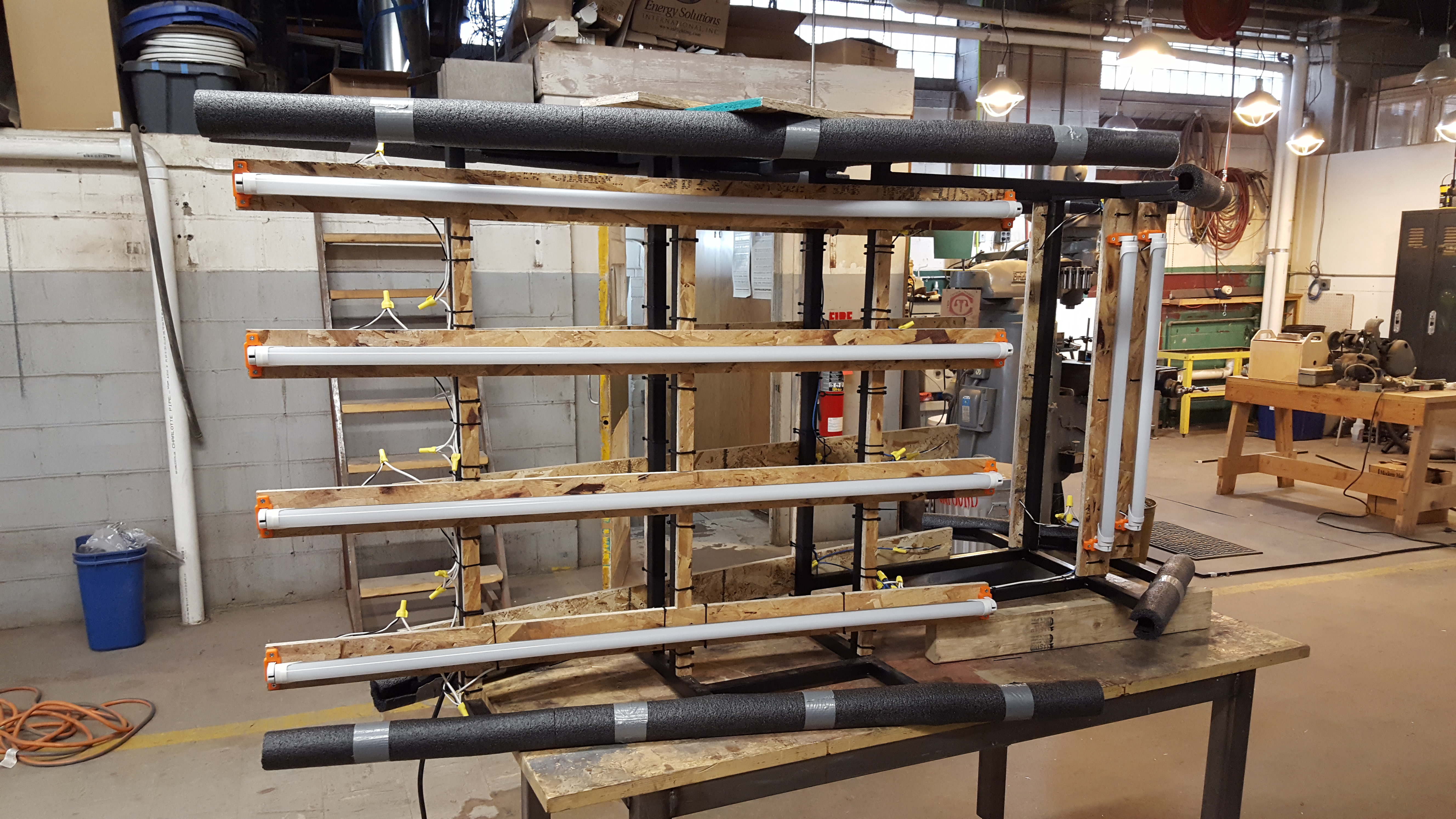
The rods I chose were 1/2″ in diameter and came in 72″ (6ft) lengths. I chose to cut these rods down into pegs measuring 2″ in length based on the thickness of the panels and baffle system. In order to allow for visitors to fill every hole on all faces of the piece I planned to create about 4,600 pegs total. This meant that I’d need 128 rods total, or 768 linear feet of stock!
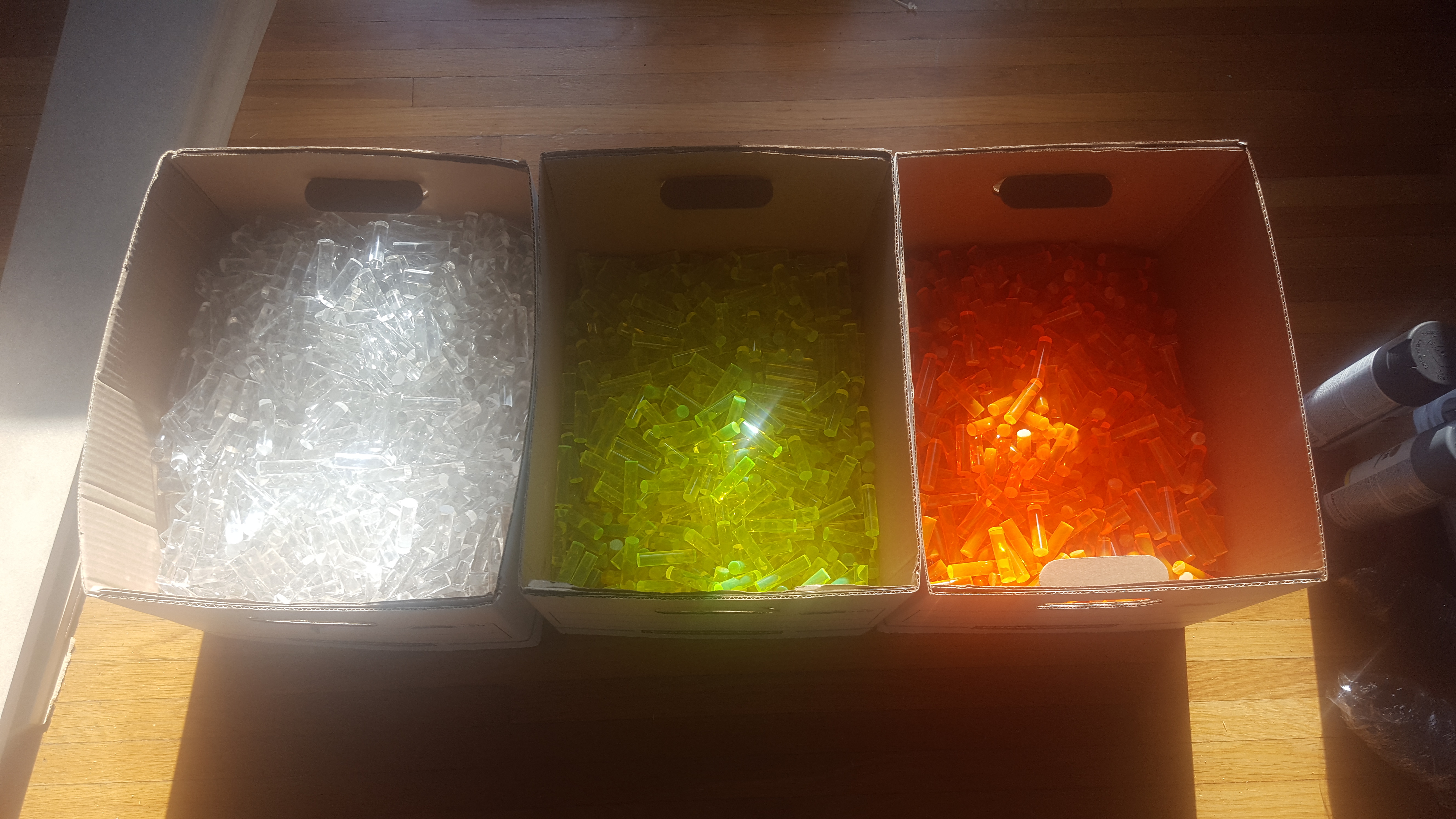
About 4,600 pegs total were fabricated, with each peg measuring 1/2″ x 2″ in size.
This required 128 rods measuring 6′ in length each for a total of 768 linear feet of stock.
Based on advice from A-1 Acrylics, I requested 50% of the stock be clear in color and the remaining amount to be split evenly between fluorescent green and orange.
Frame
After every part of the project was fully designed, planned out, and sourced, I decided to first tackle the fabrication of the internal steel structure upon which all of the panels and lights would be attached, if for no other reason than because I knew I’d need to learn the most in order to make it. Before this project I had never even seen welding equipment in person, let alone welding anything myself, but thanks to the wonderful metalworking shop at my local hackerspace (Hack Factory / TC Maker) and the experienced guidance of it’s managers (Clara Schiller and Steve Skalko) I was up and running in no time!
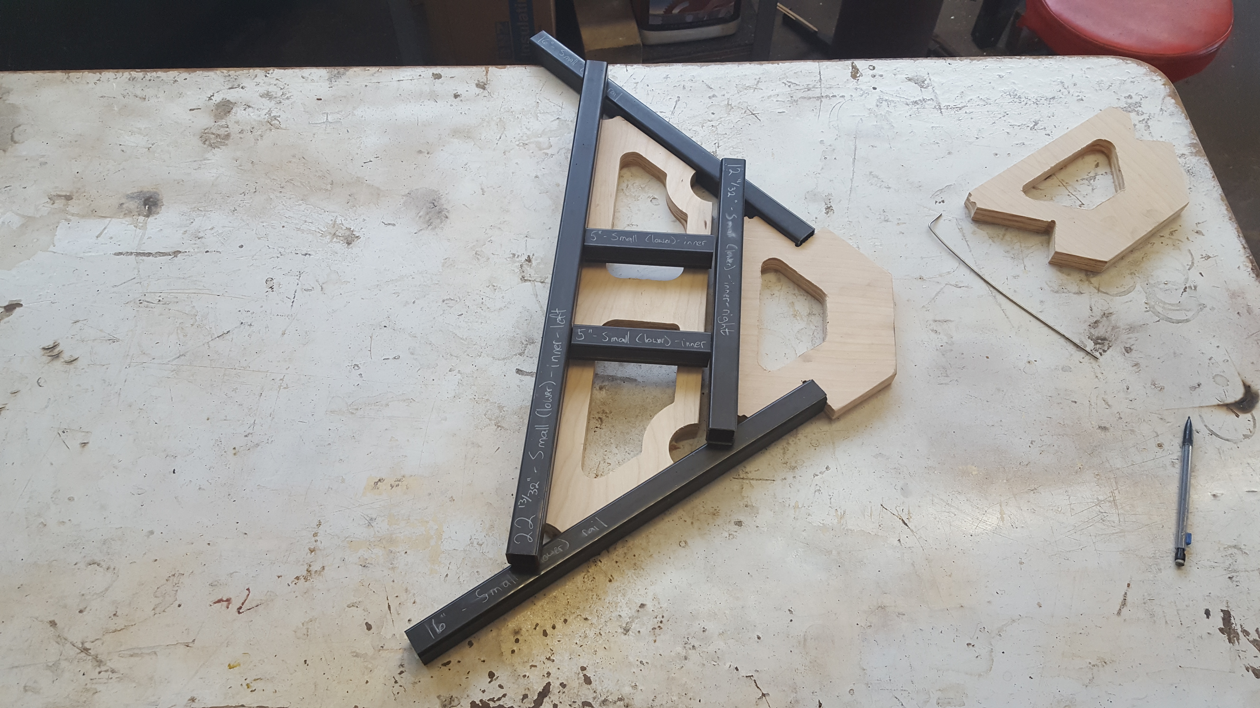
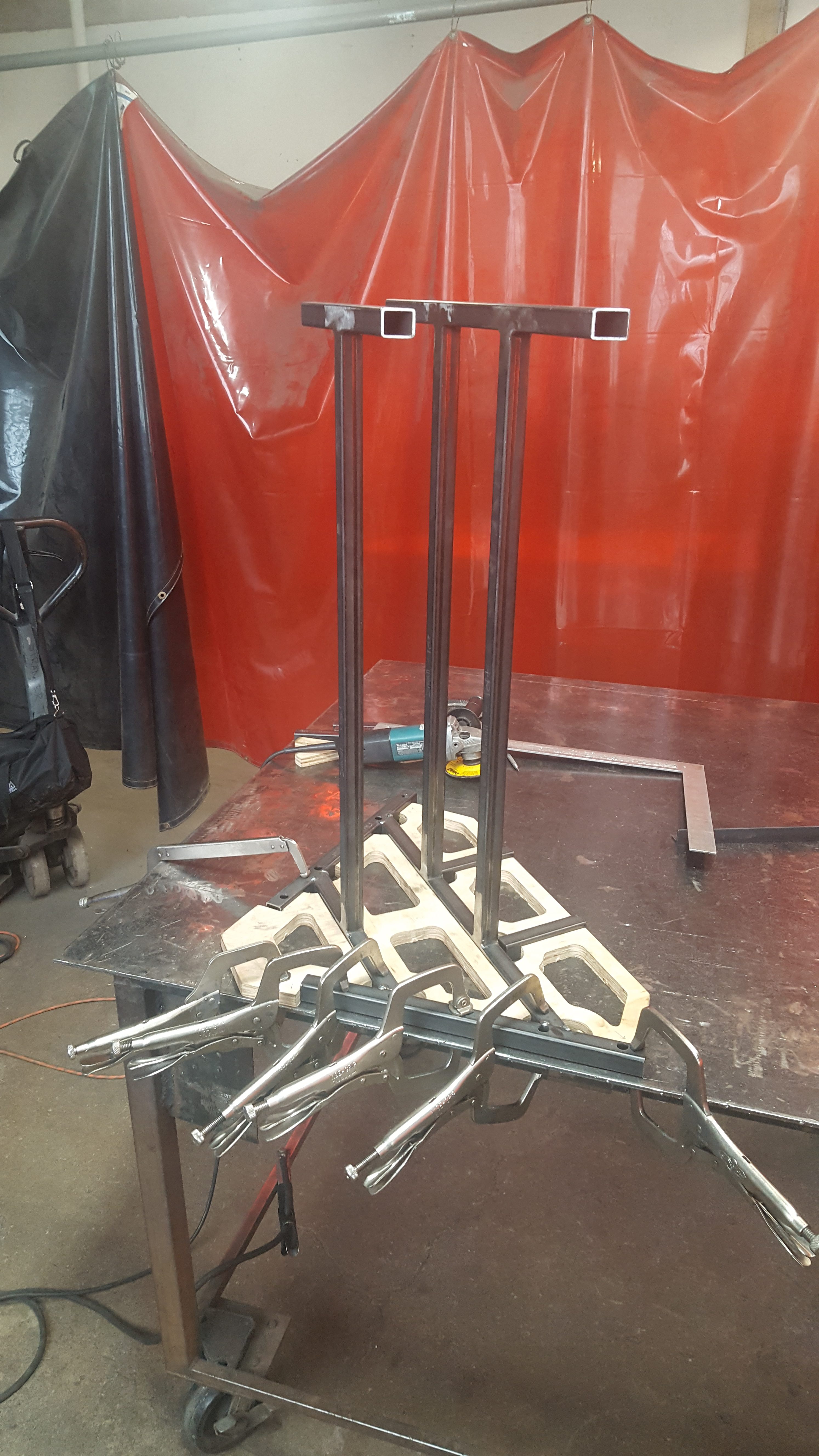
CNC wood templates
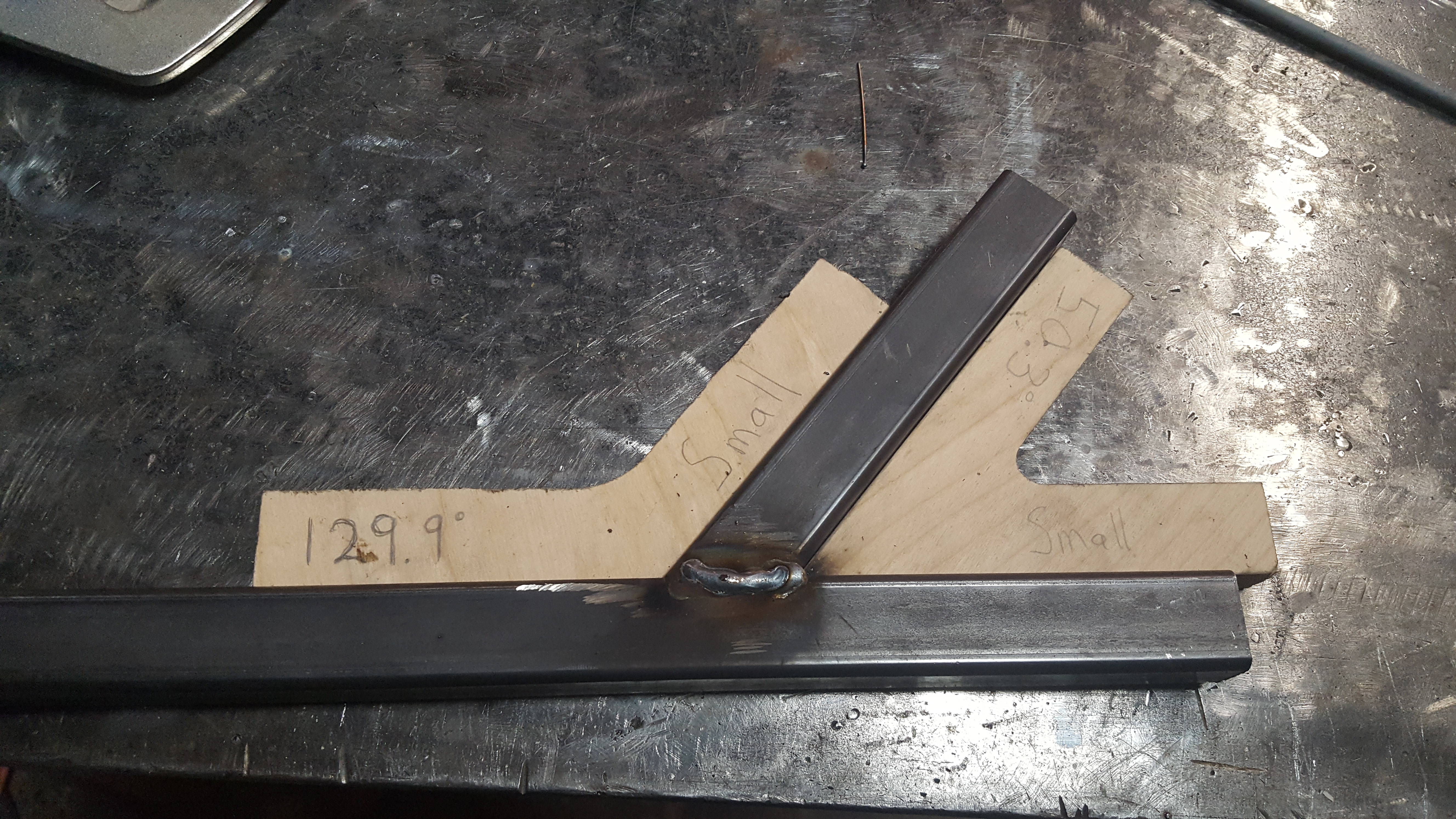
Even with some modest training and practice, I knew from the start that I should not underestimate the difficulty of this part of the project, especially when it comes to the level of accuracy I wanted compared to the reality of what is possible when working with with basic shop tools. To maximize my chances of success I decided to leverage my background in digital fabrication to create some highly accurate “throwaway” wood templates that would allow me to create near-perfect assemblies even if individual steel pieces were slightly imperfectly cut.
In Fusion 360 I extruded the negative space between and around joints that I wanted to weld together, then removed material from the middle of each piece to allow for easier clamping to the steel stock. I also made sure to remove material from the corners as well to prevent the wood from catching on fire during the welding process, and to allow some clearance in case I wanted to add fillet welds later on. I also created some angled pieces for each unique angle throughout the design so that I could very easily verify joints during and after welding.
All of these templates were then CNC’d out of 3/4″ “birch” plywood using a very temperamental hand-built 4×4′ CNC machine at the TC Maker hackerspace.
In hindsight I would say the decision to create and use these wood templates turned out to be one of the most critical factors in for success in this project, and I really don’t know how I could’ve achieved the results I wanted without them!
Metal preparation
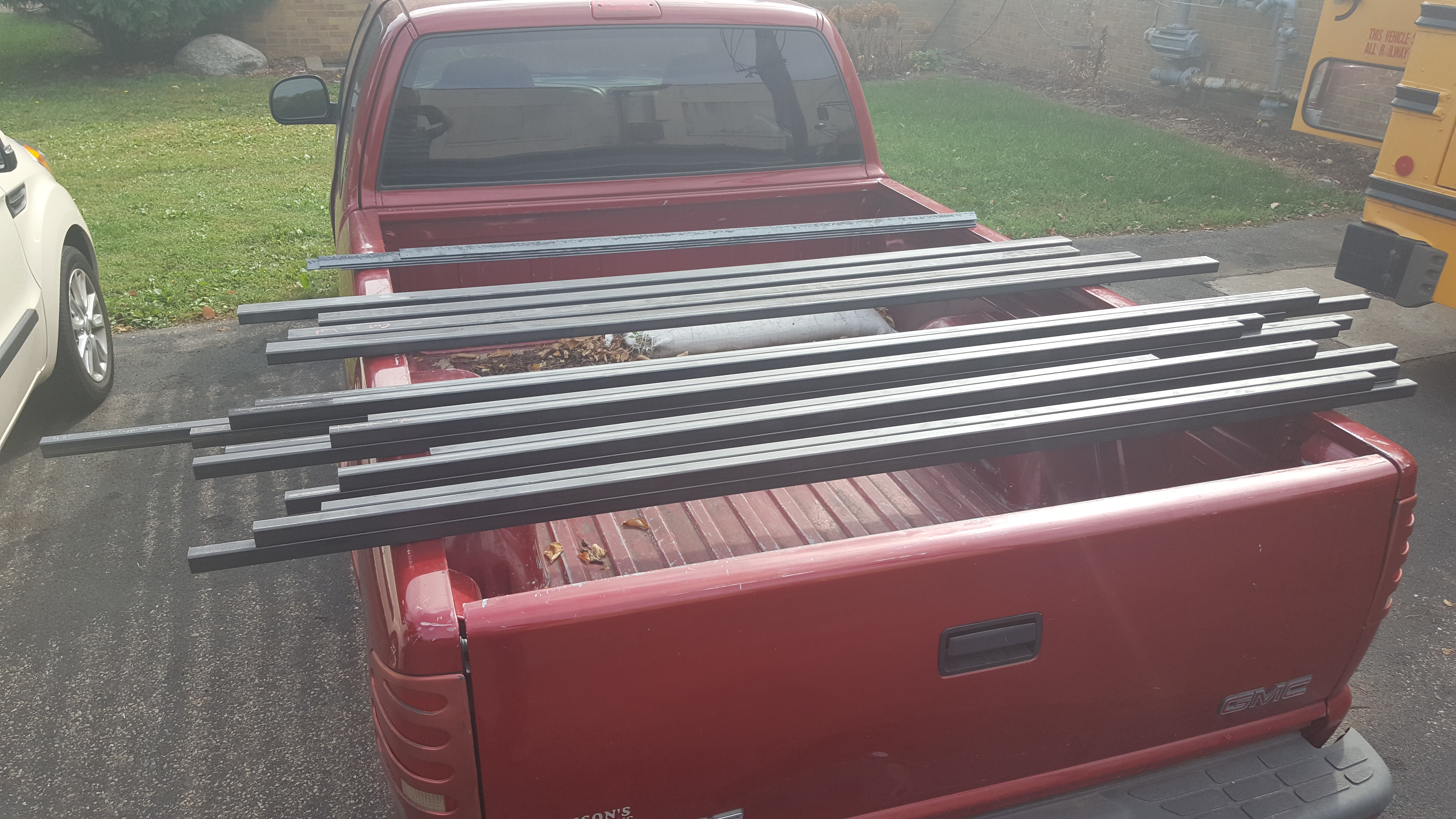
Using my Fusion 360 design for reference I created a cutlist for all the steel stock I needed and calculated the total lengths I would need to buy. I ended up buying nearly 100′ of 1″ square tubing for the frame, along with 24′ of 1″ angle iron for the panel mounting solution and 24″ of 1×2″ tubing for the base. Since these all came in 12′ lengths, which is a tad too long for my pickup, I asked my steel dealer (the wonderful Discount Steel) to cut them all roughly in half based on my cutlist.
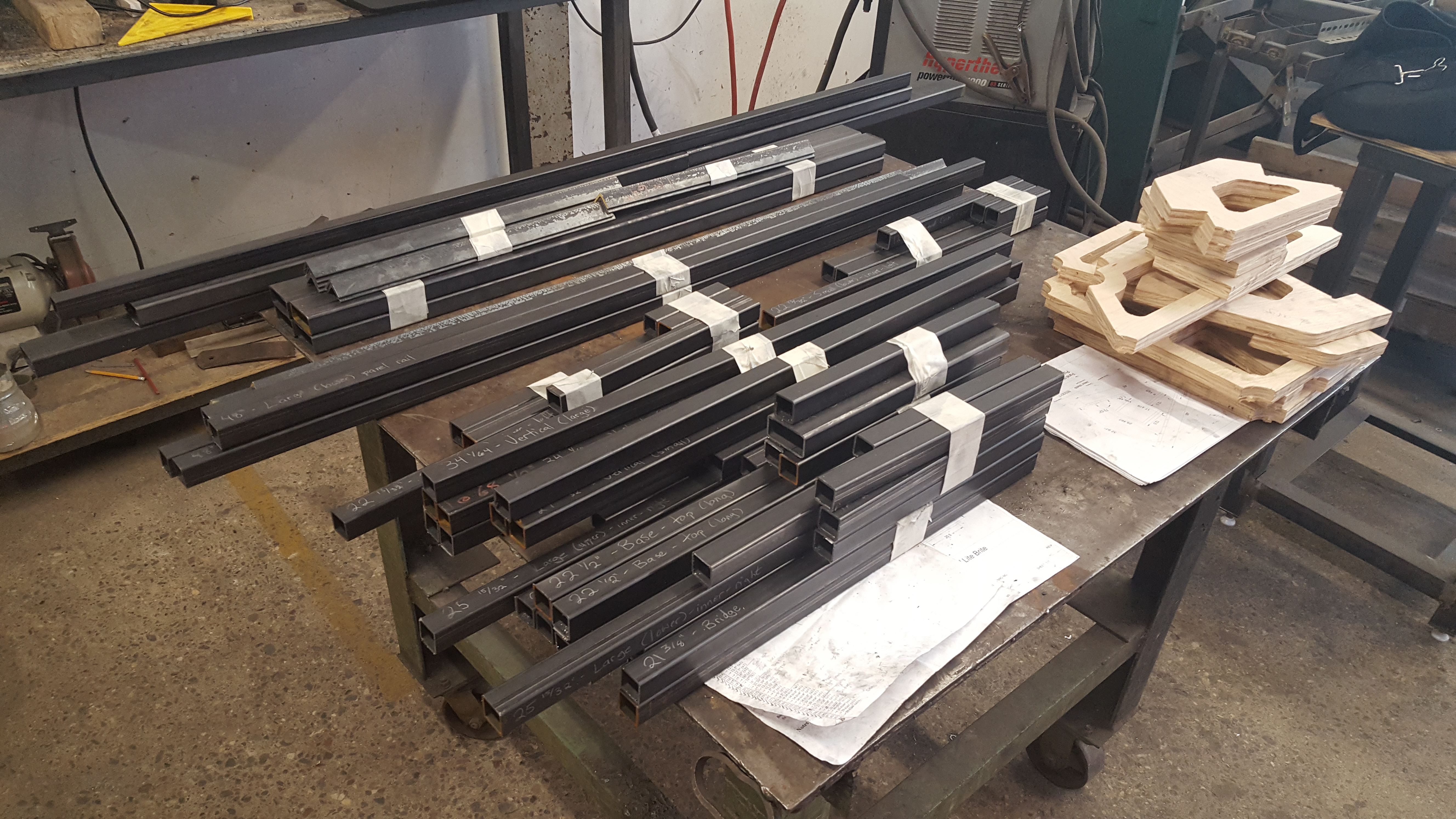
Using a horizontal bandsaw I first cut all pieces from the stock within about 1/16″ or less of the necessary lengths, ending up with about 60 pieces overall and very little waste. Shoutout to Jon Overholt for the very useful cutlist web app!
I then carefully marked and cut all the angles into the ends of each length that needed them using the horizontal bandsaw. To do this I used a digital angle finder to set the angle of the bandsaw’s fence to within half a degree of what I needed, which was surprisingly effective.
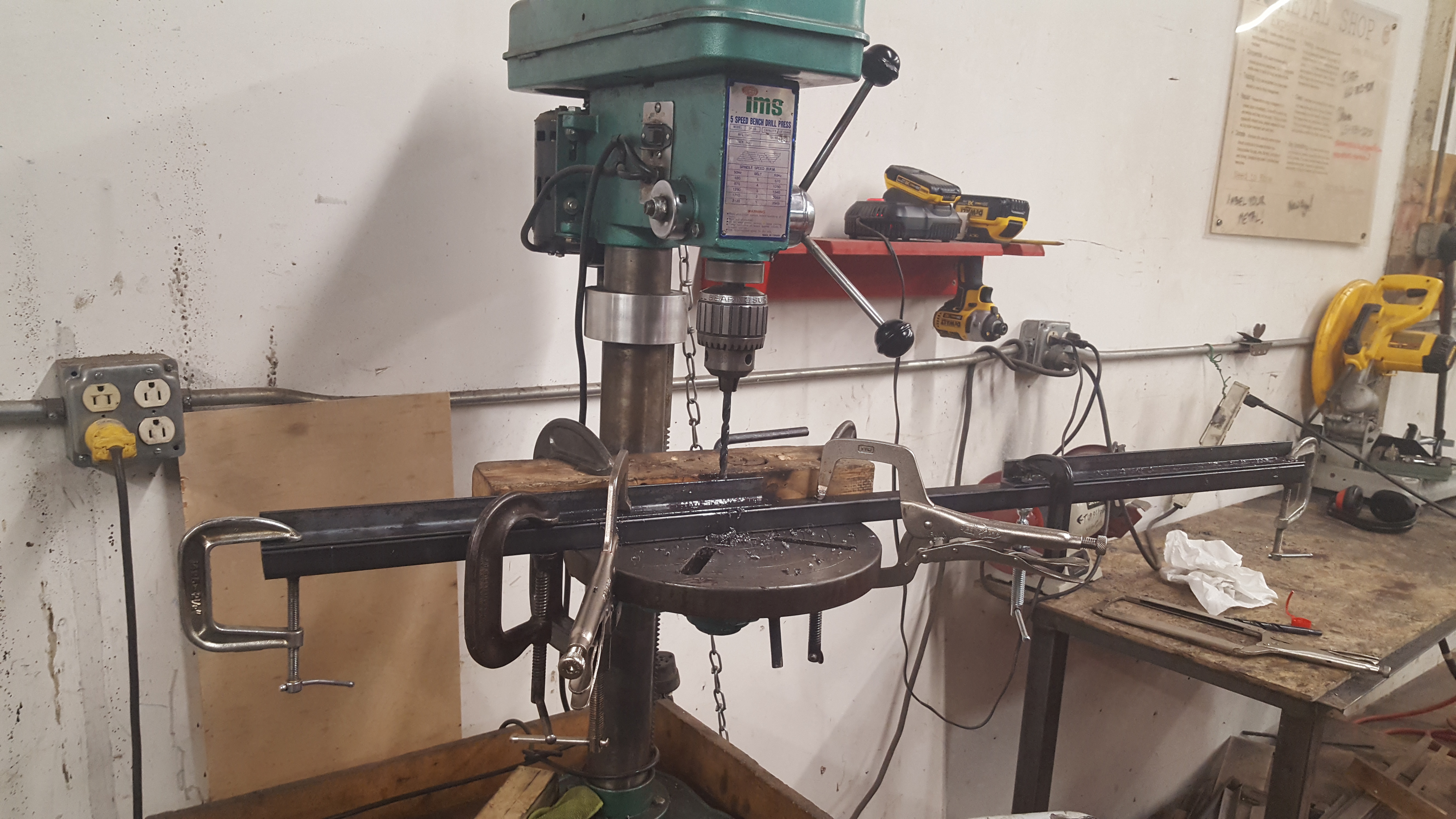
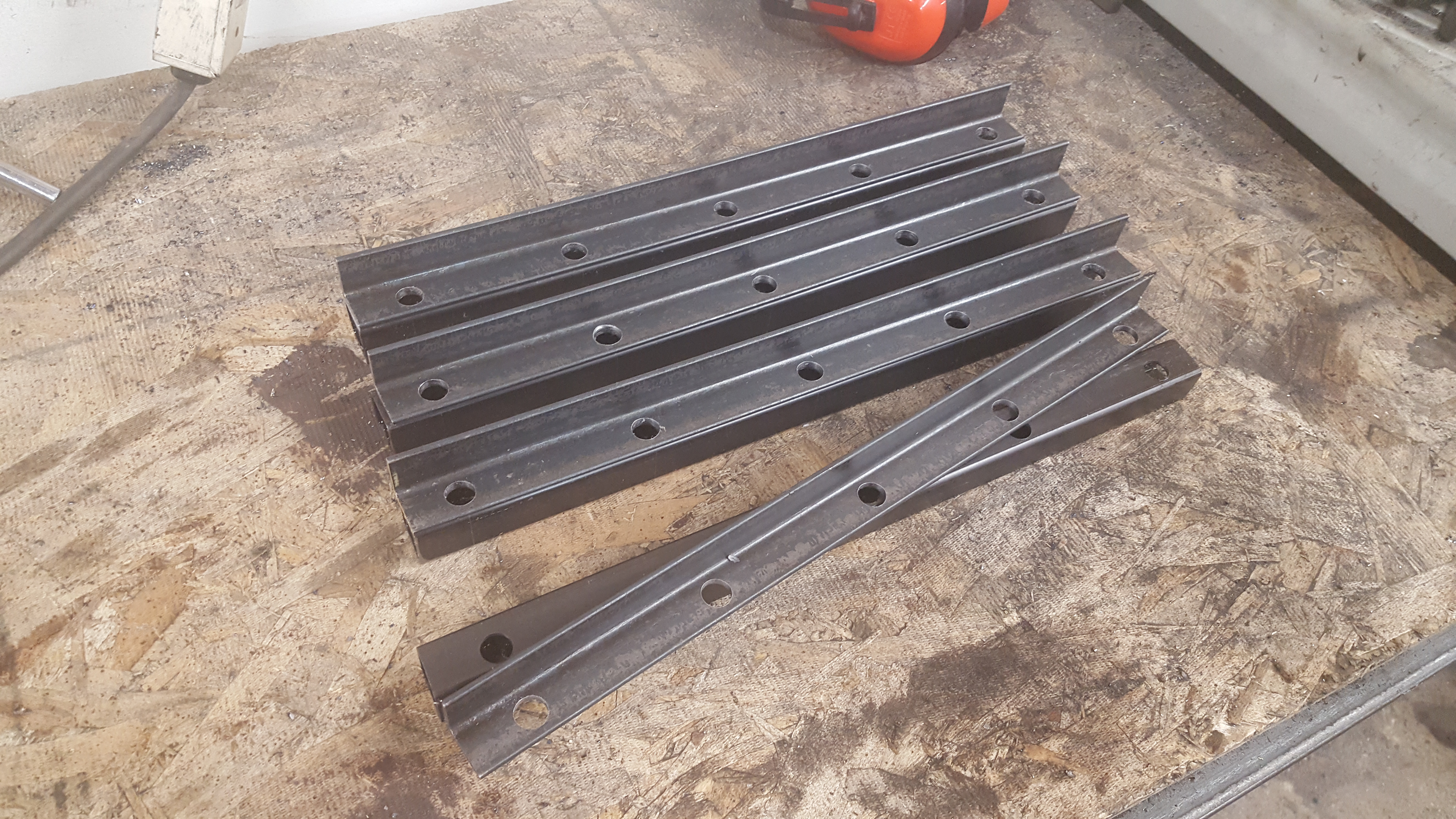
Once all the pieces had been cut to length and deburred on a bench grinder, I then needed to drill a series of paired holes in the angle iron and their accompanying square tubing sections in order to create a mounting system for all of the outer plywood panels to be fabricated later. These angle iron pieces would be permanently attached to the plywood panels so they could be “hung” onto the frame and secured using 1/2″ lag bolts.

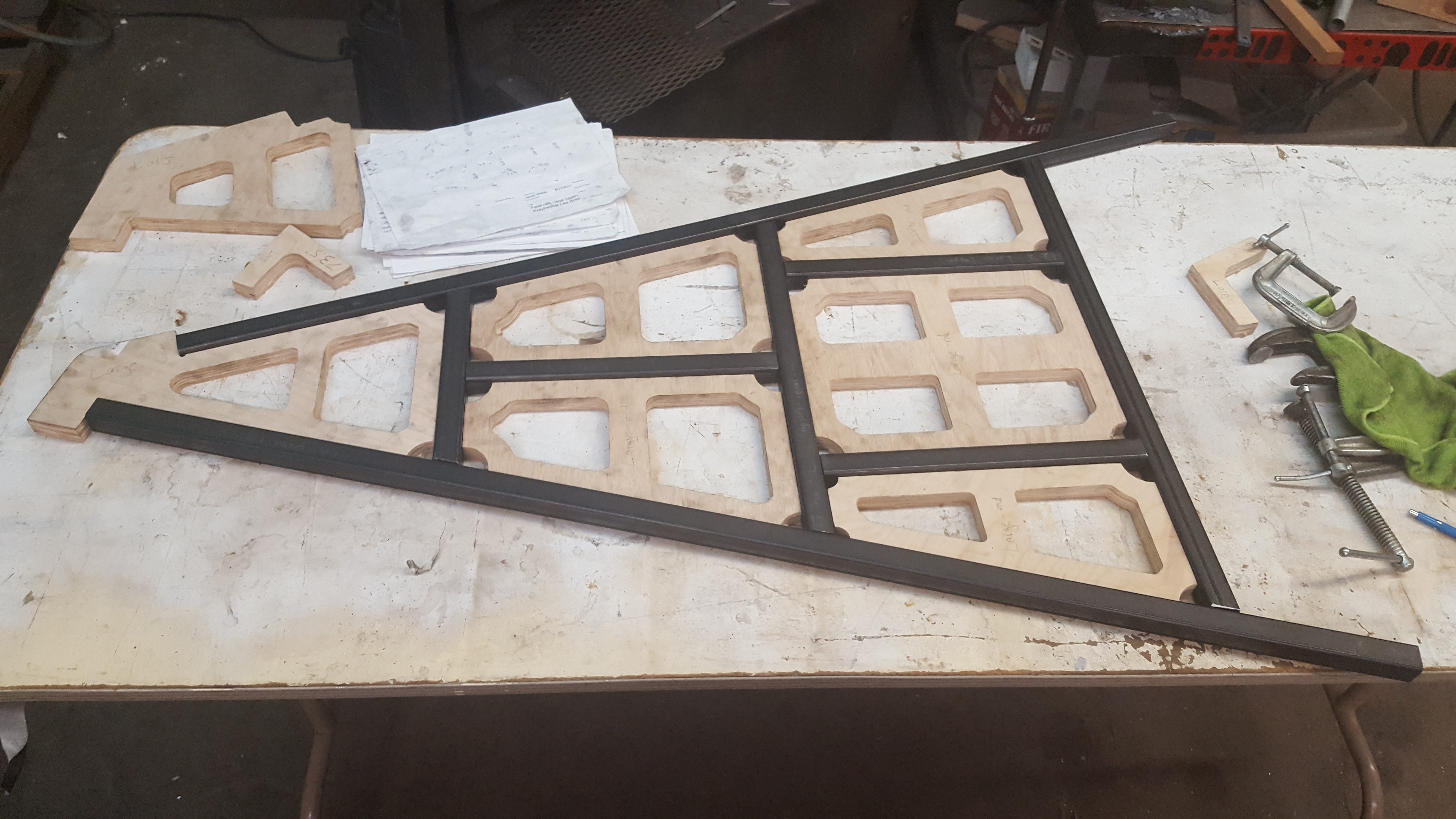
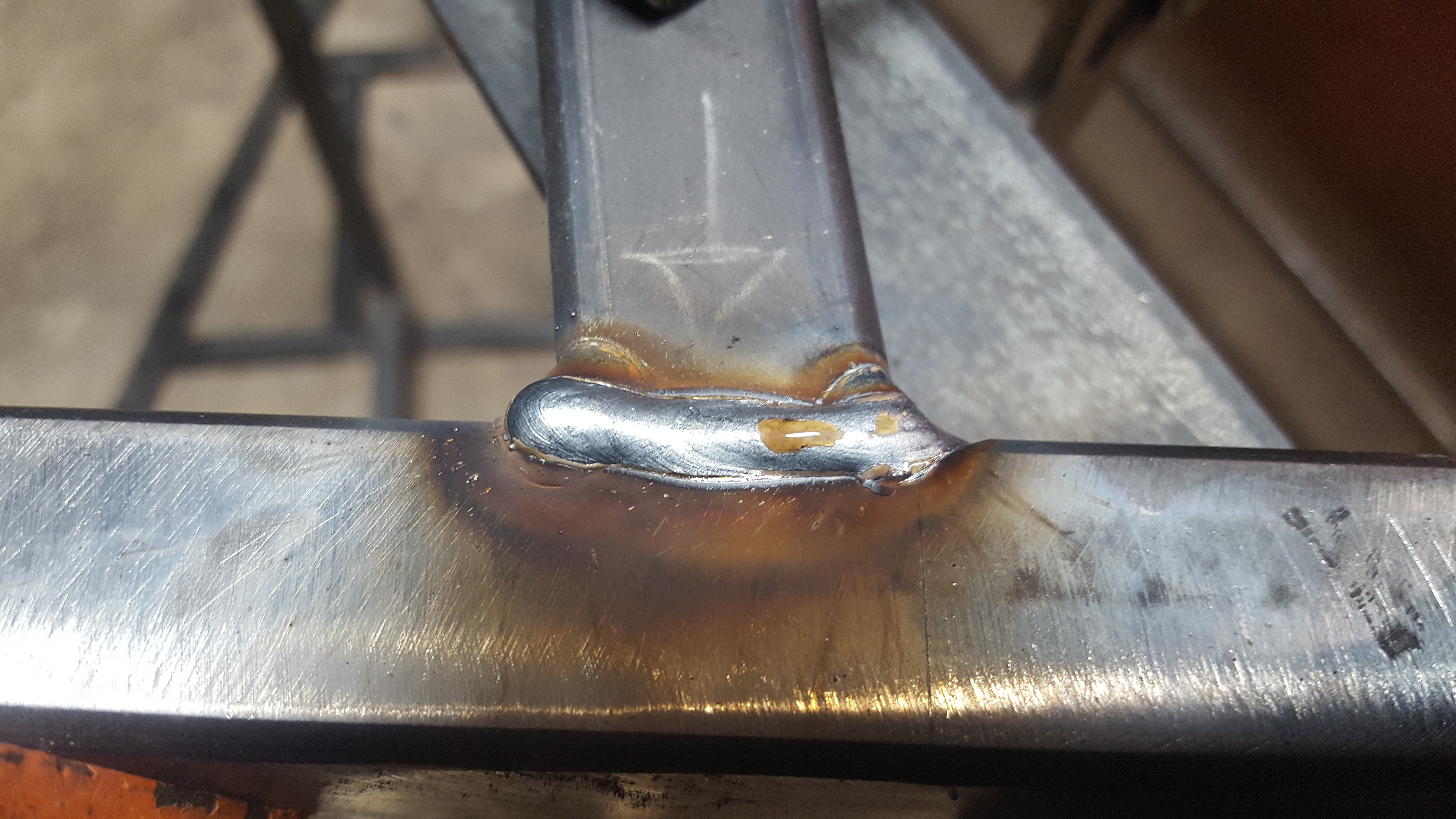
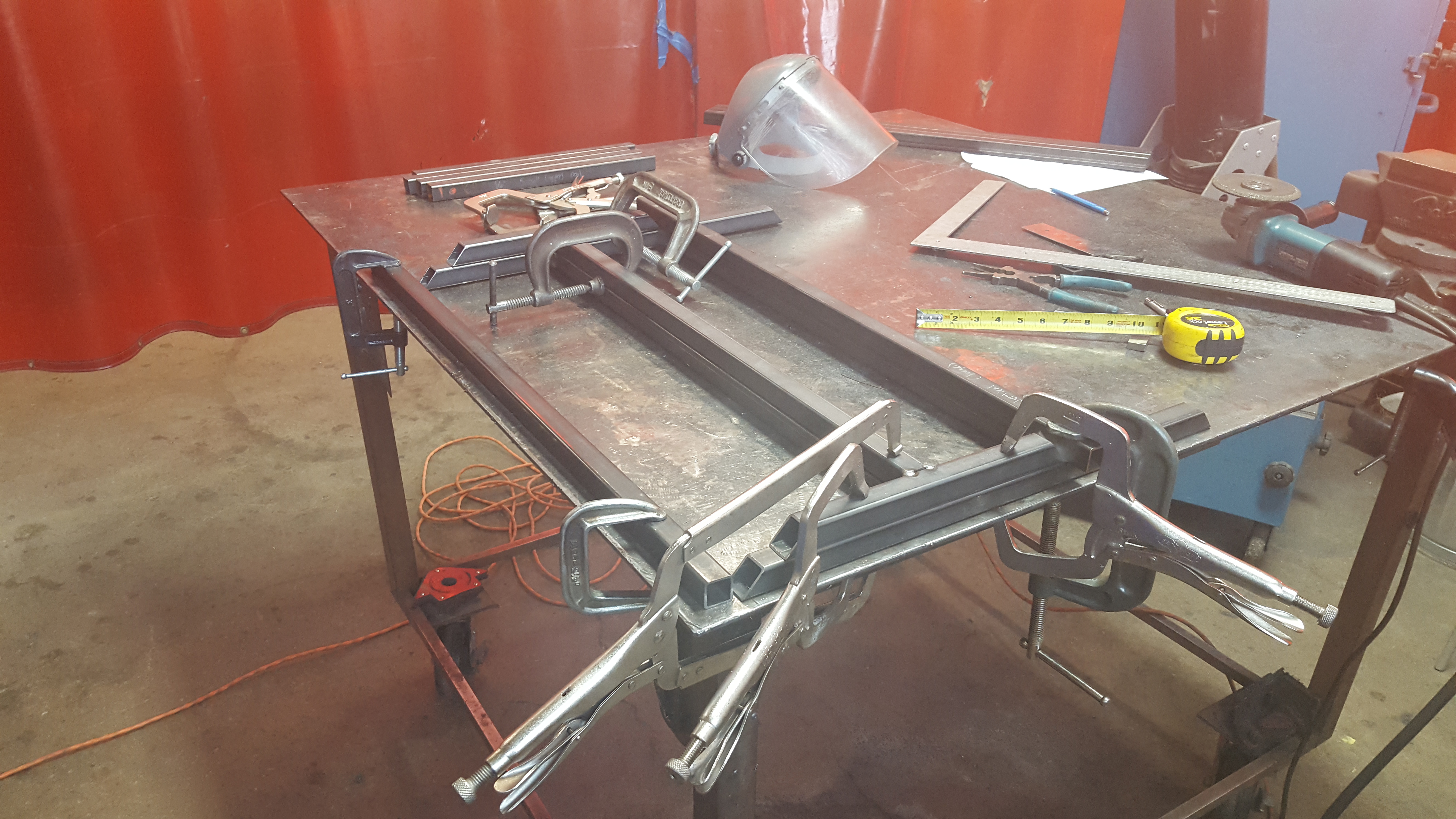
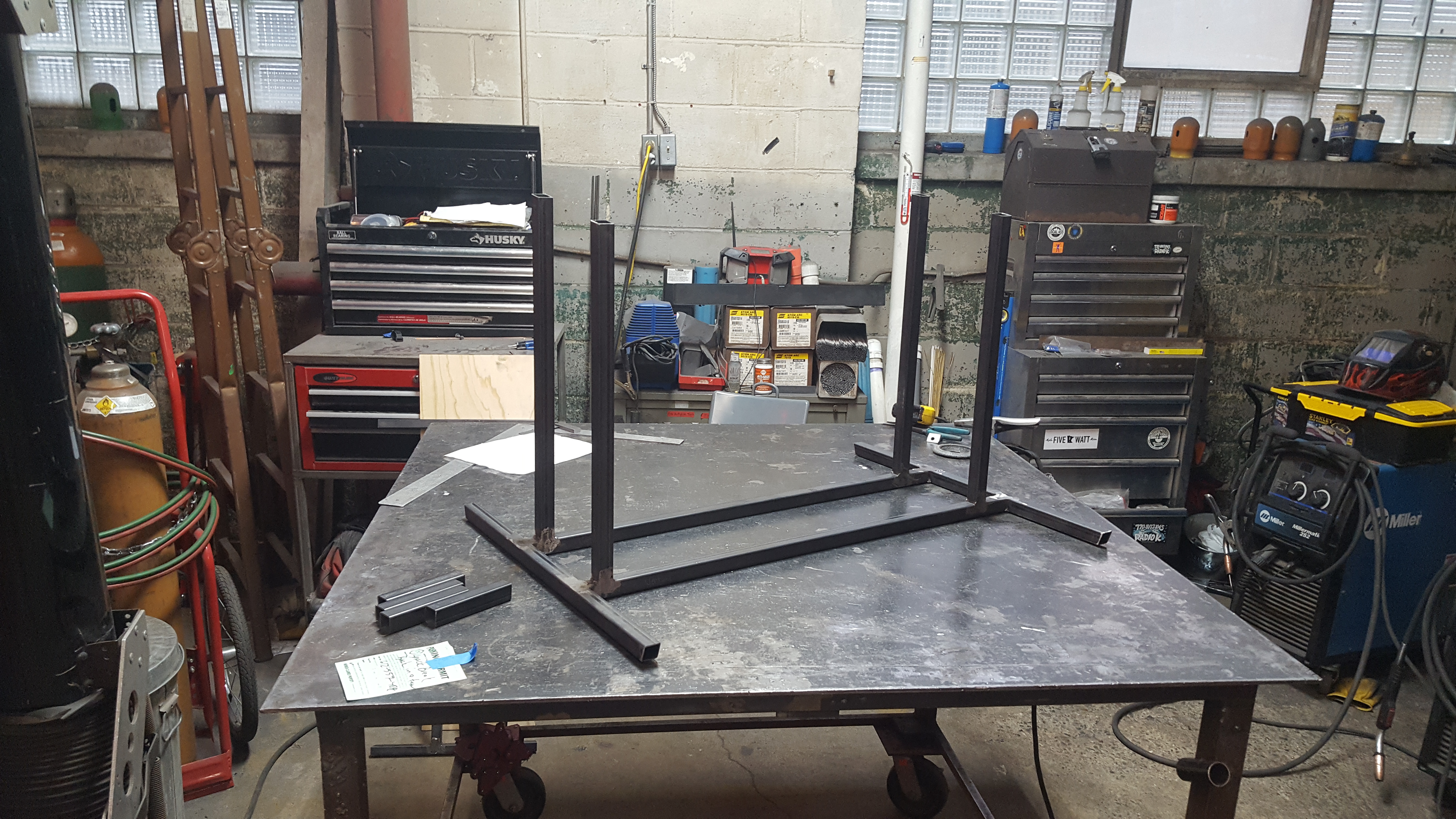
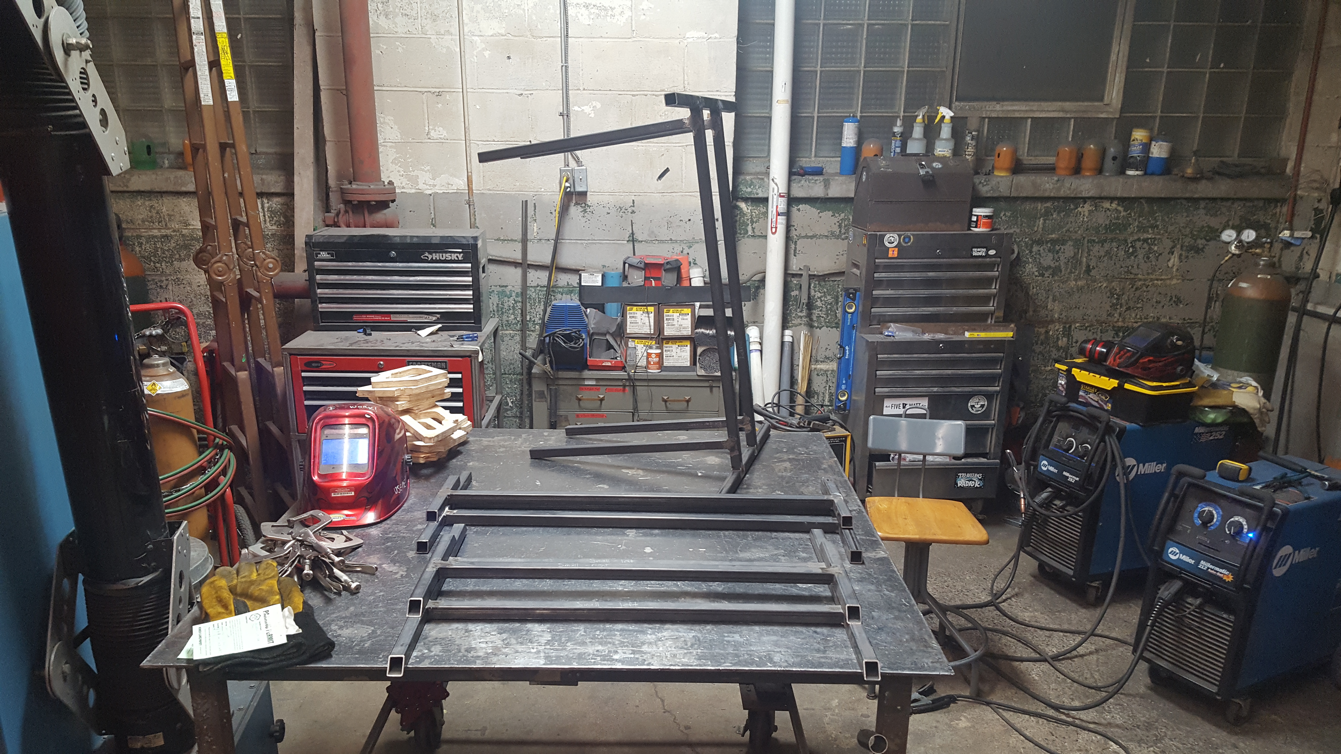
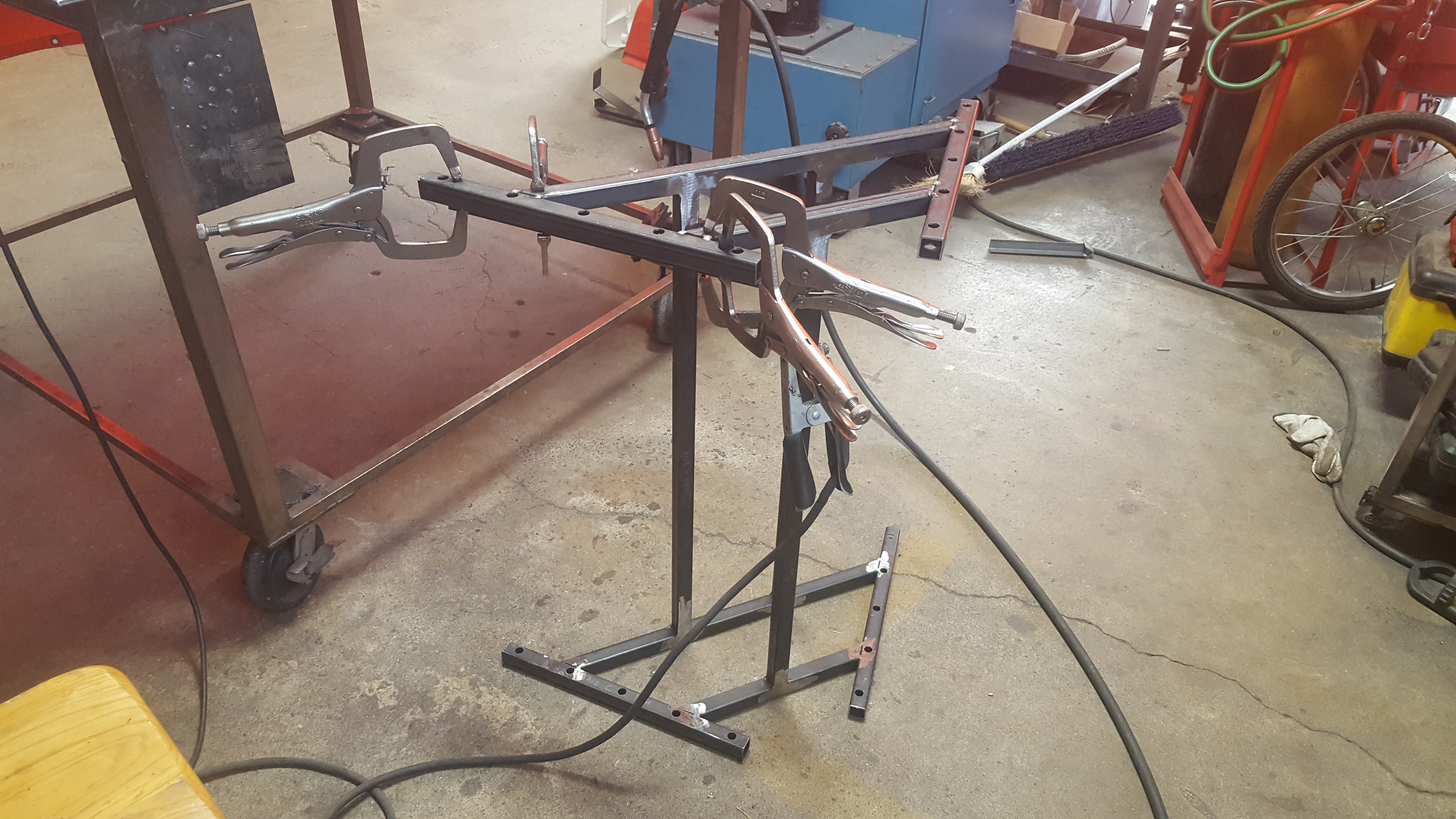
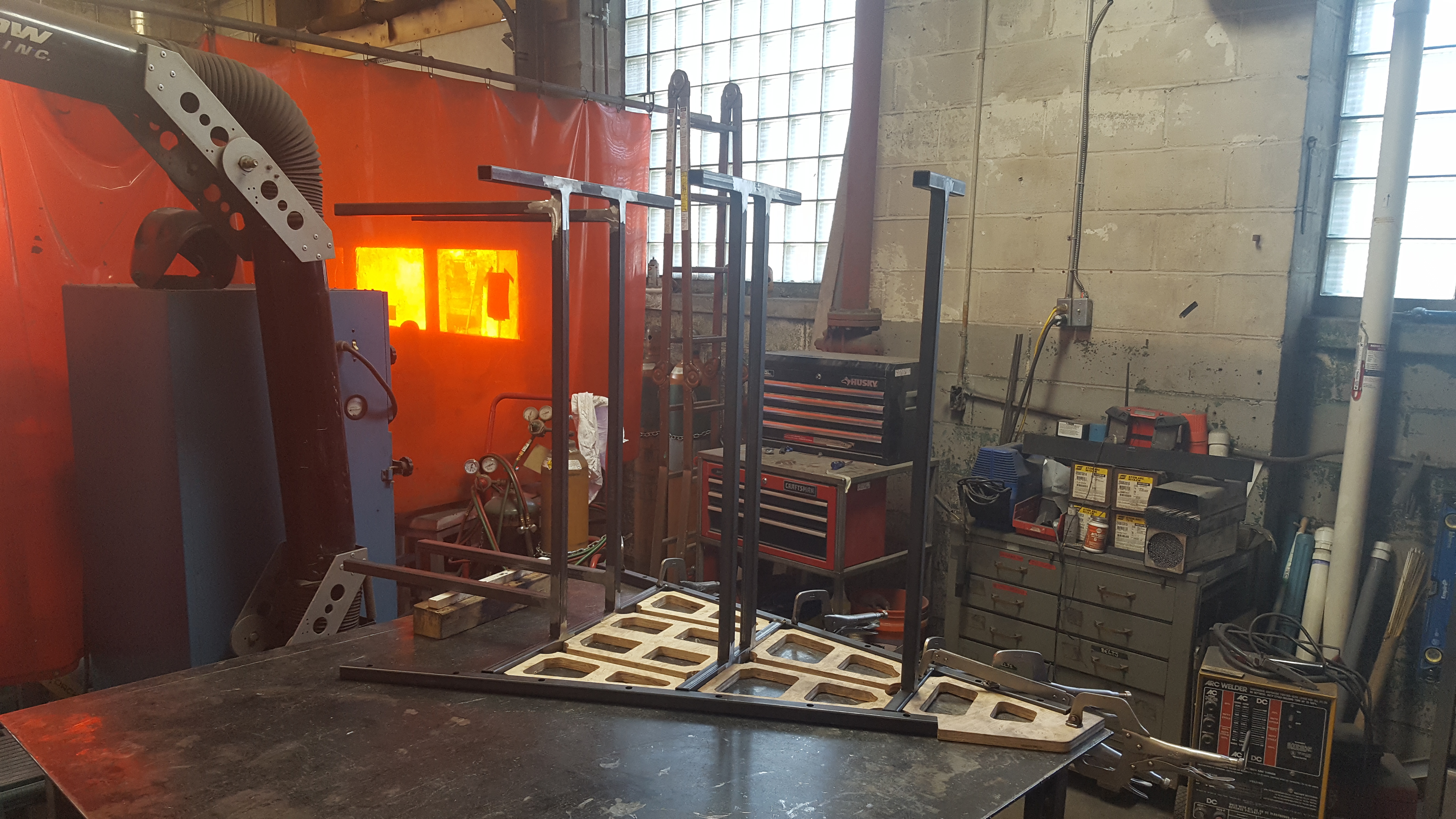
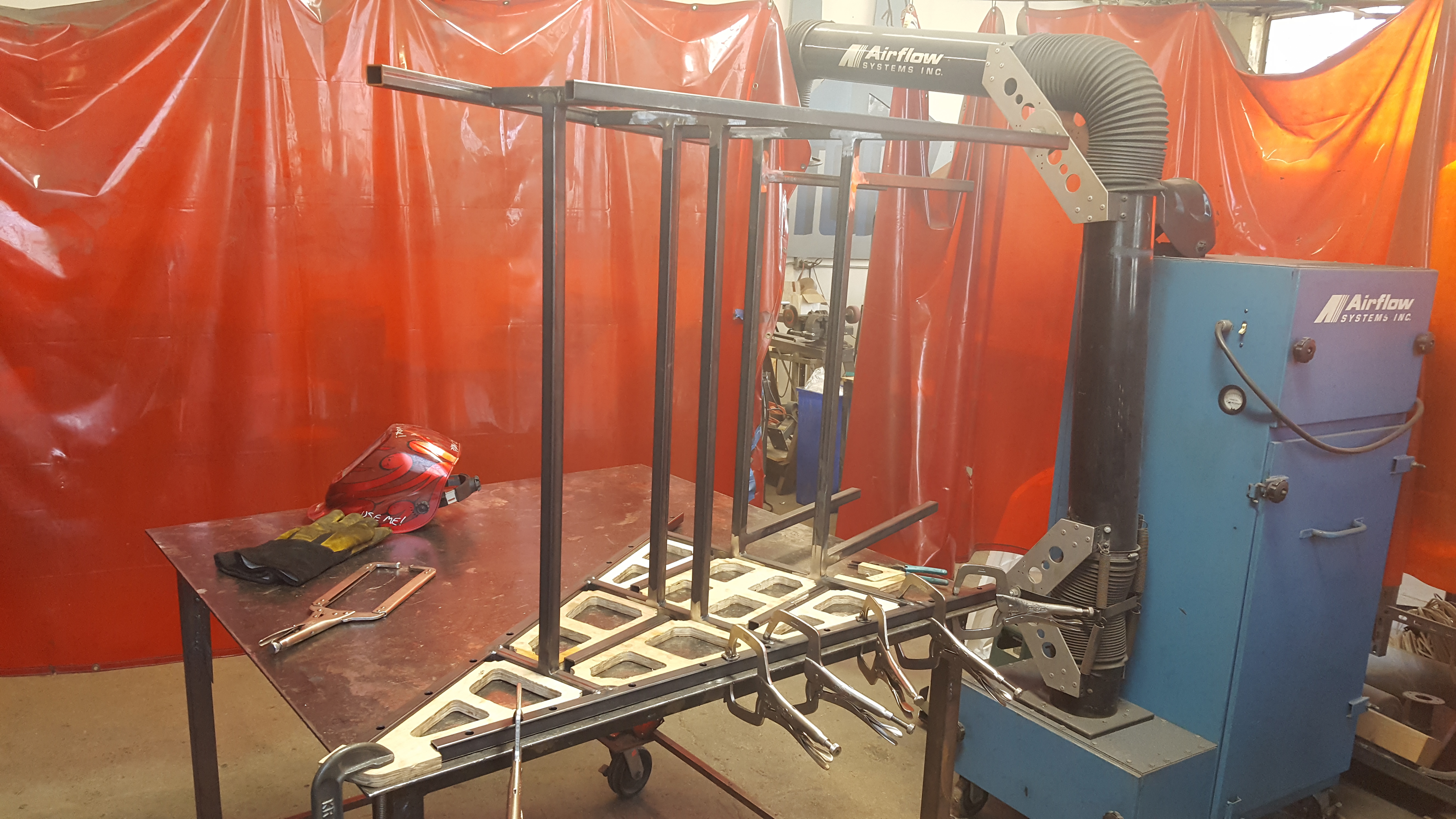
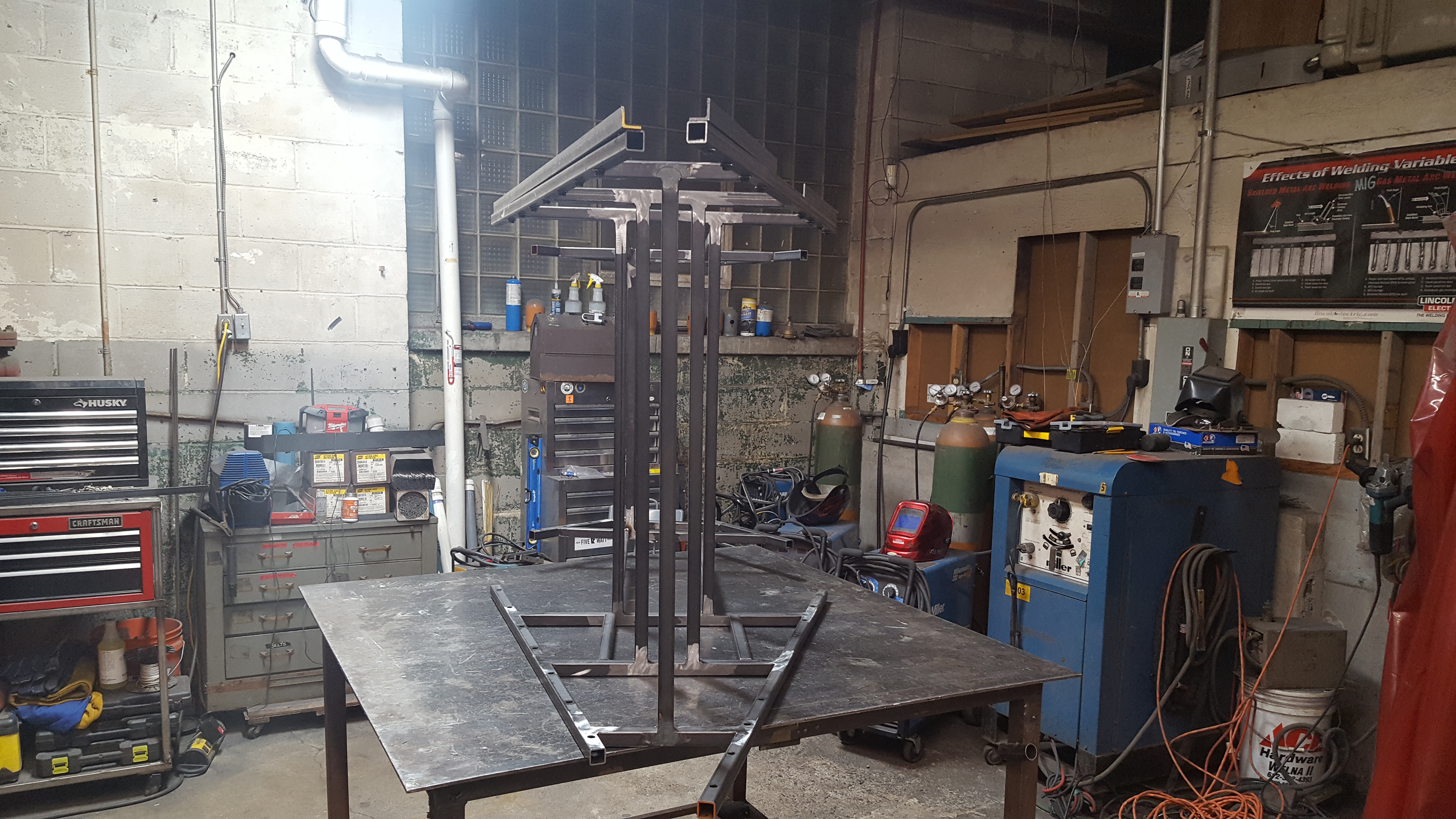
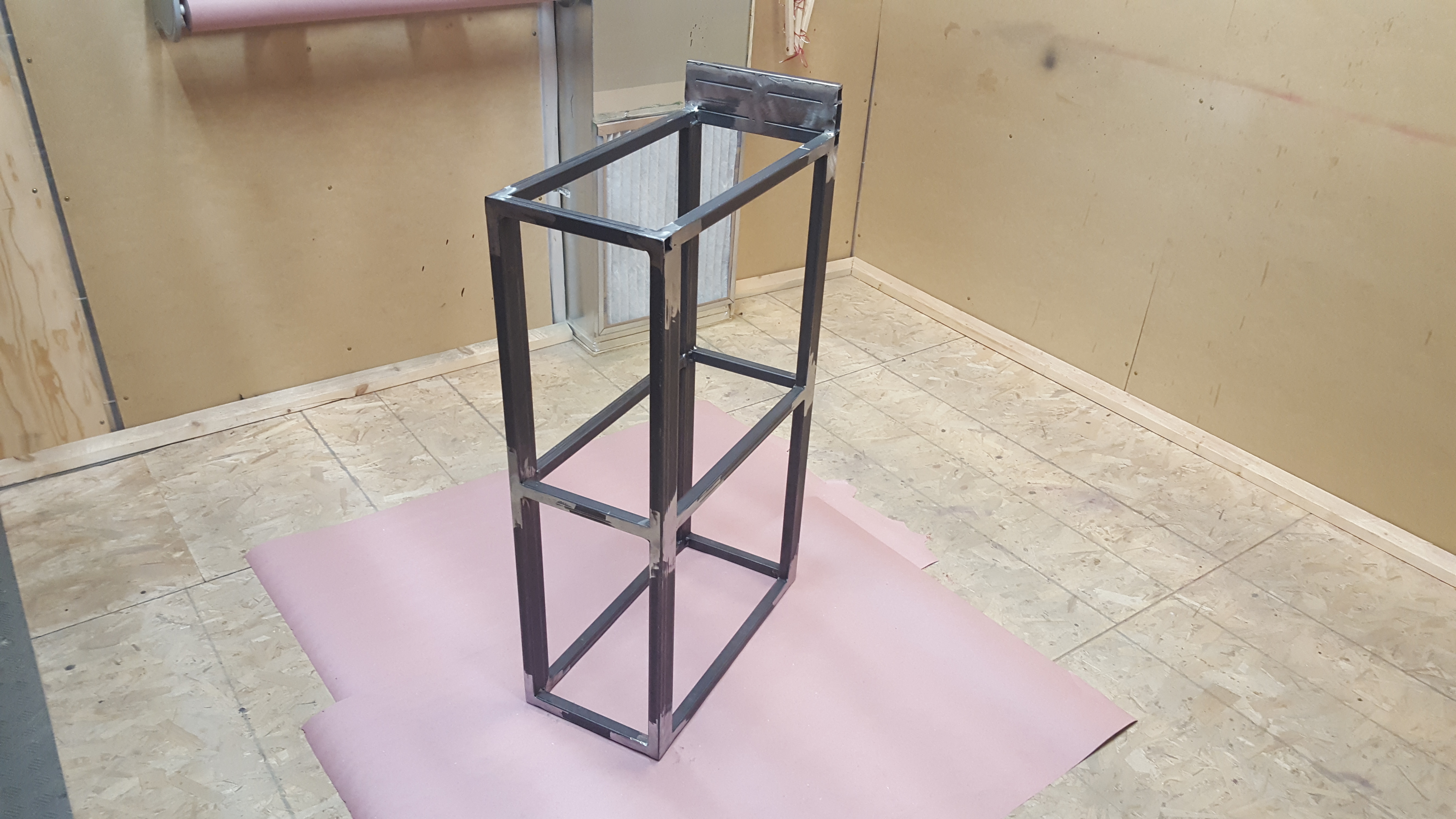
Welding
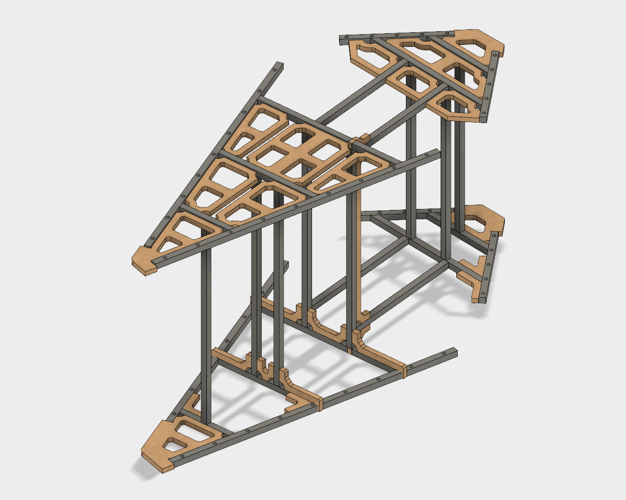
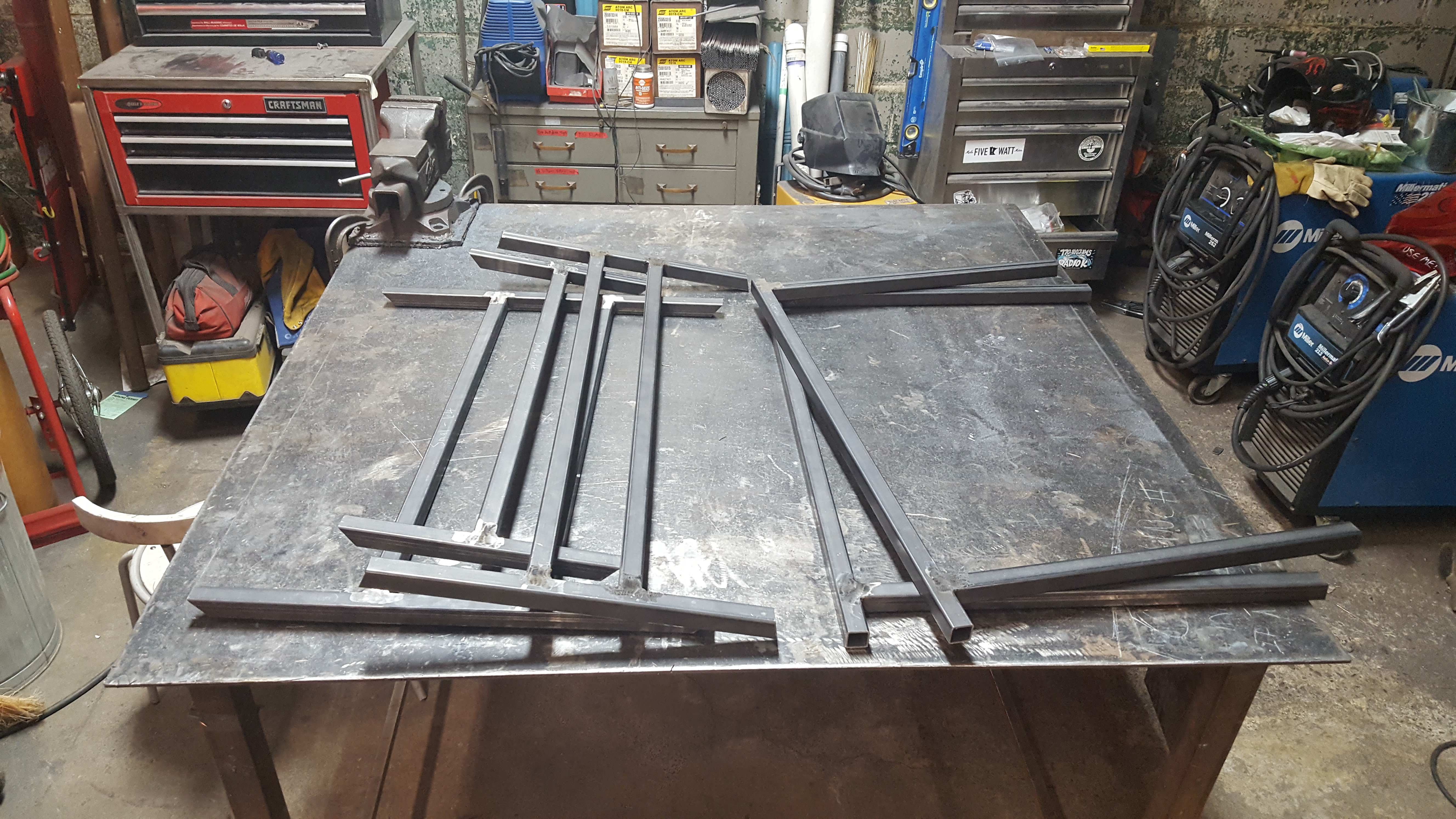
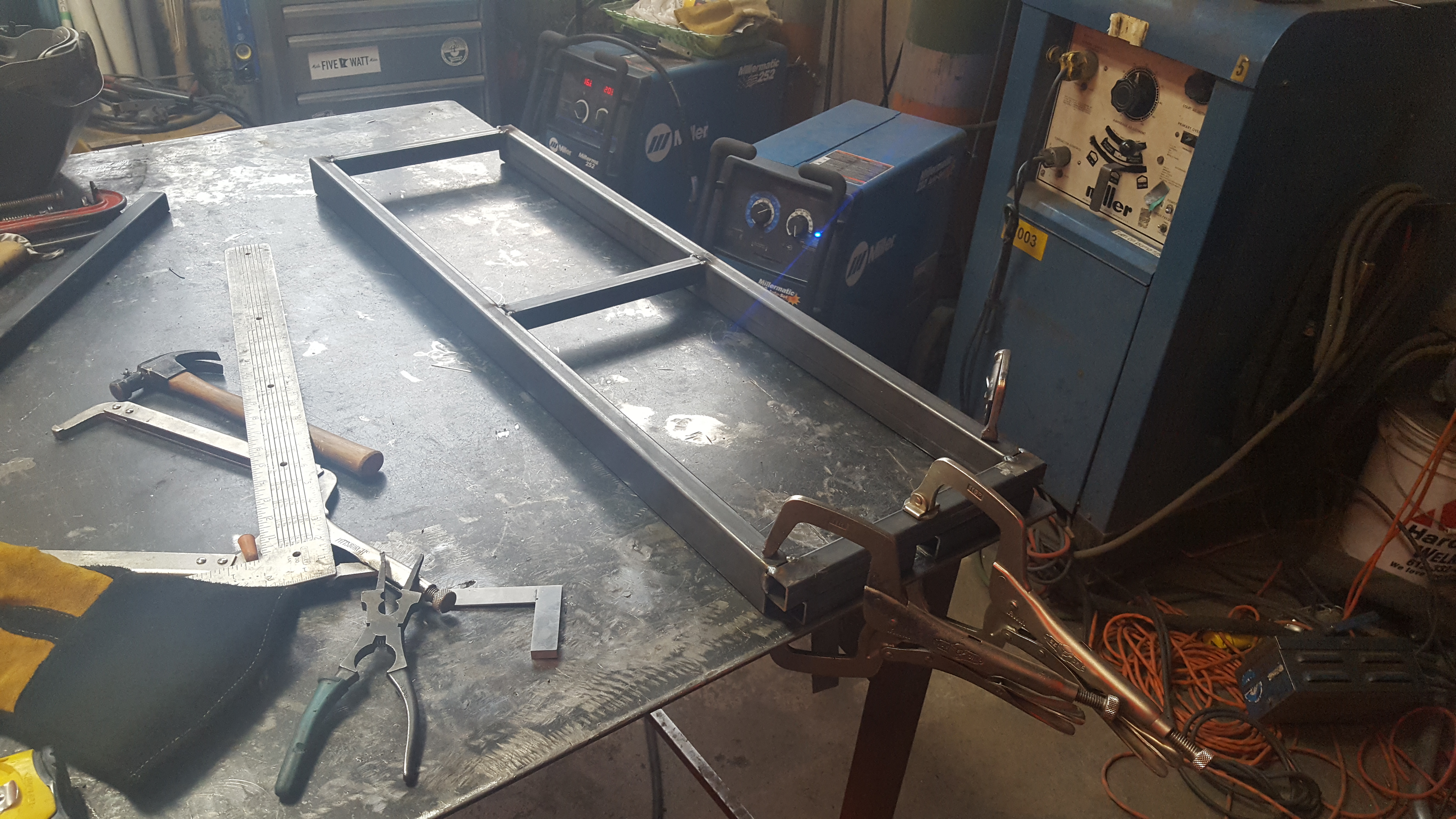
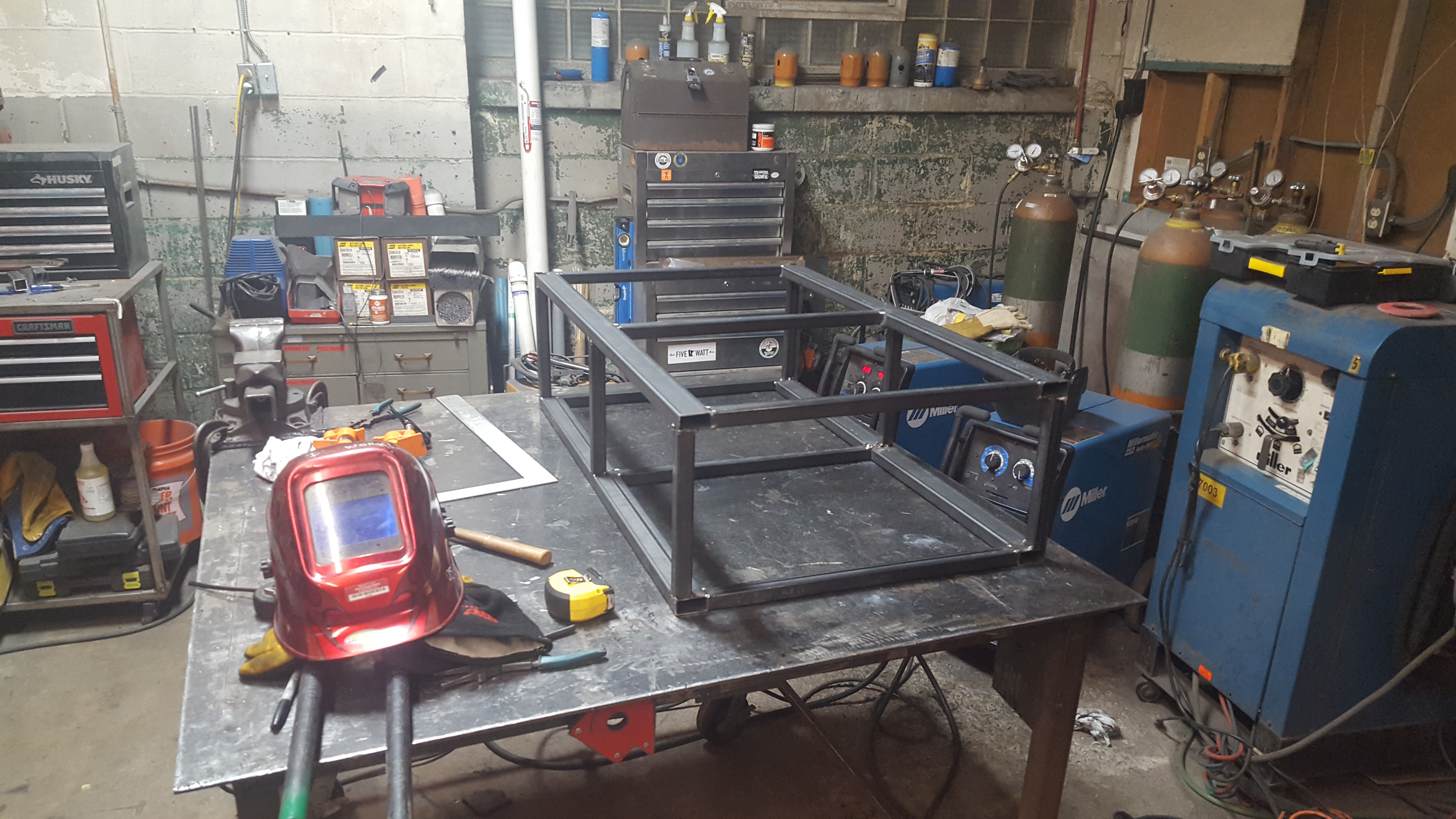
With the steel tubing cut to size and the CNC wood templates fabricated, I then set about welding the frame together as a series of sub-assemblies. Using a Miller MIG welder I started by individually welding each of the vertical assemblies that join and align pairs of crossbeams from the parallel horizontal triangular planes.
Next I carefully welded each of the long outer rails (with holes for mounting the outer plywood panels later) to these vertical assemblies, resulting in two complete triangular “halves”. Finally these two halves were joined together using horizontal tubing to create the completed frame.
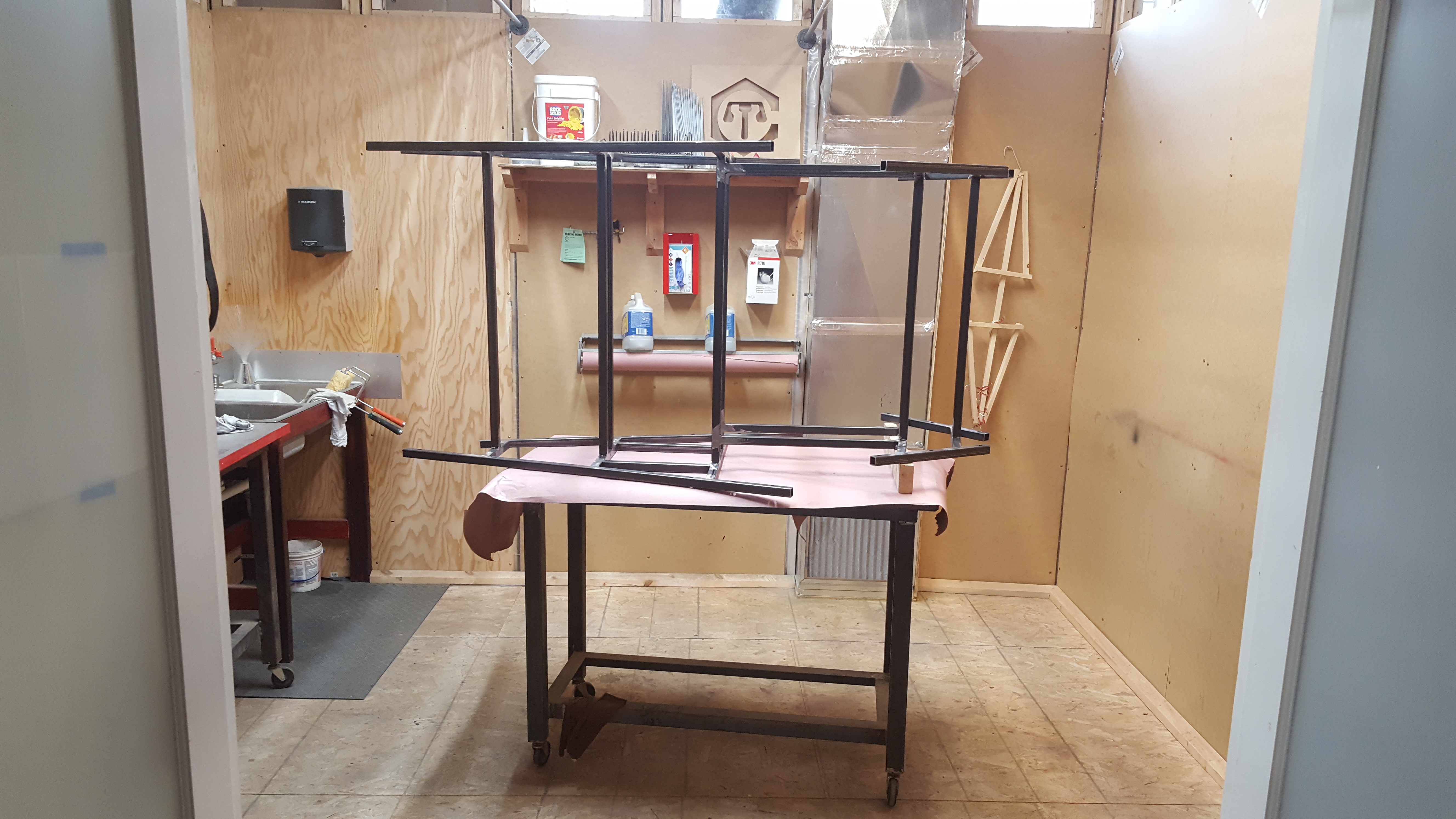
In this case, a picture really is worth a thousand words:


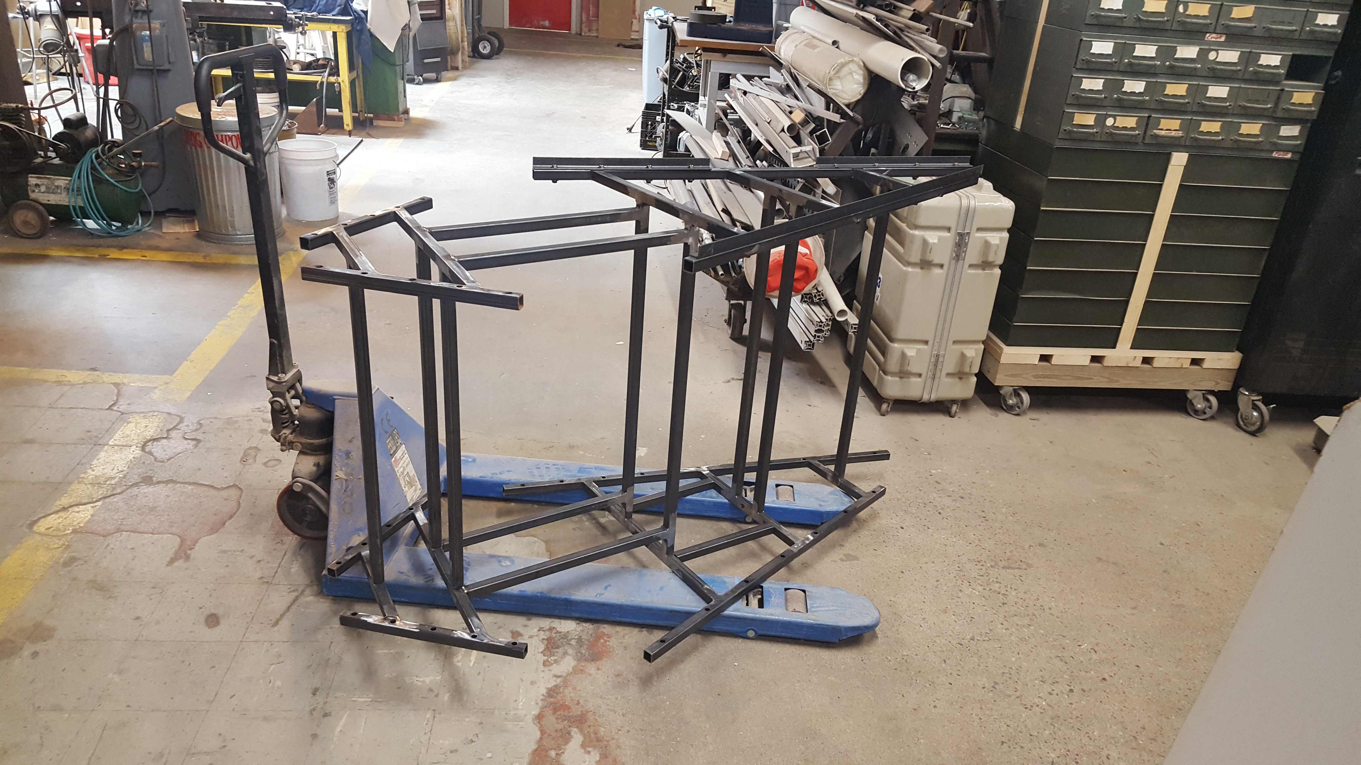
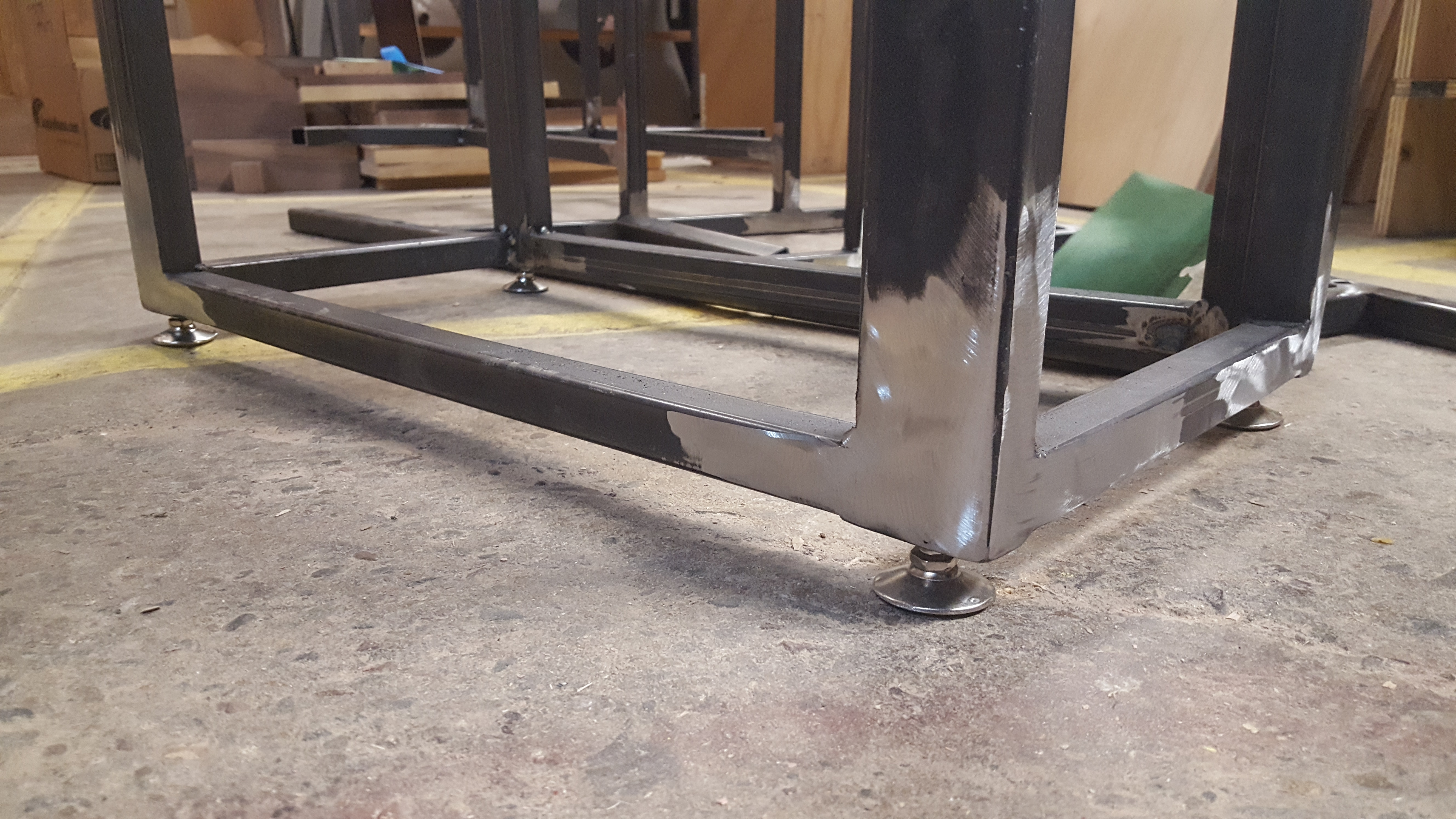
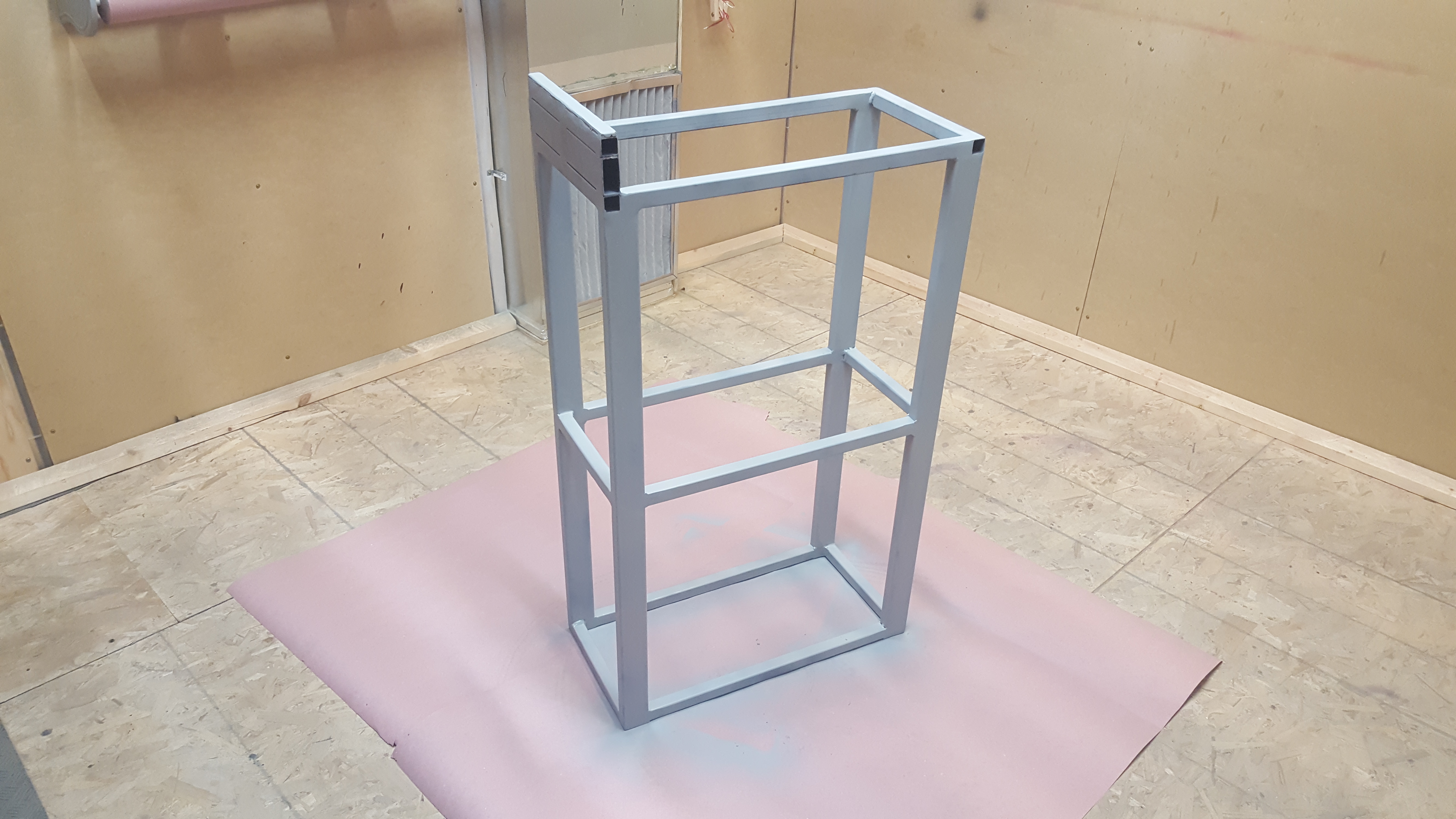
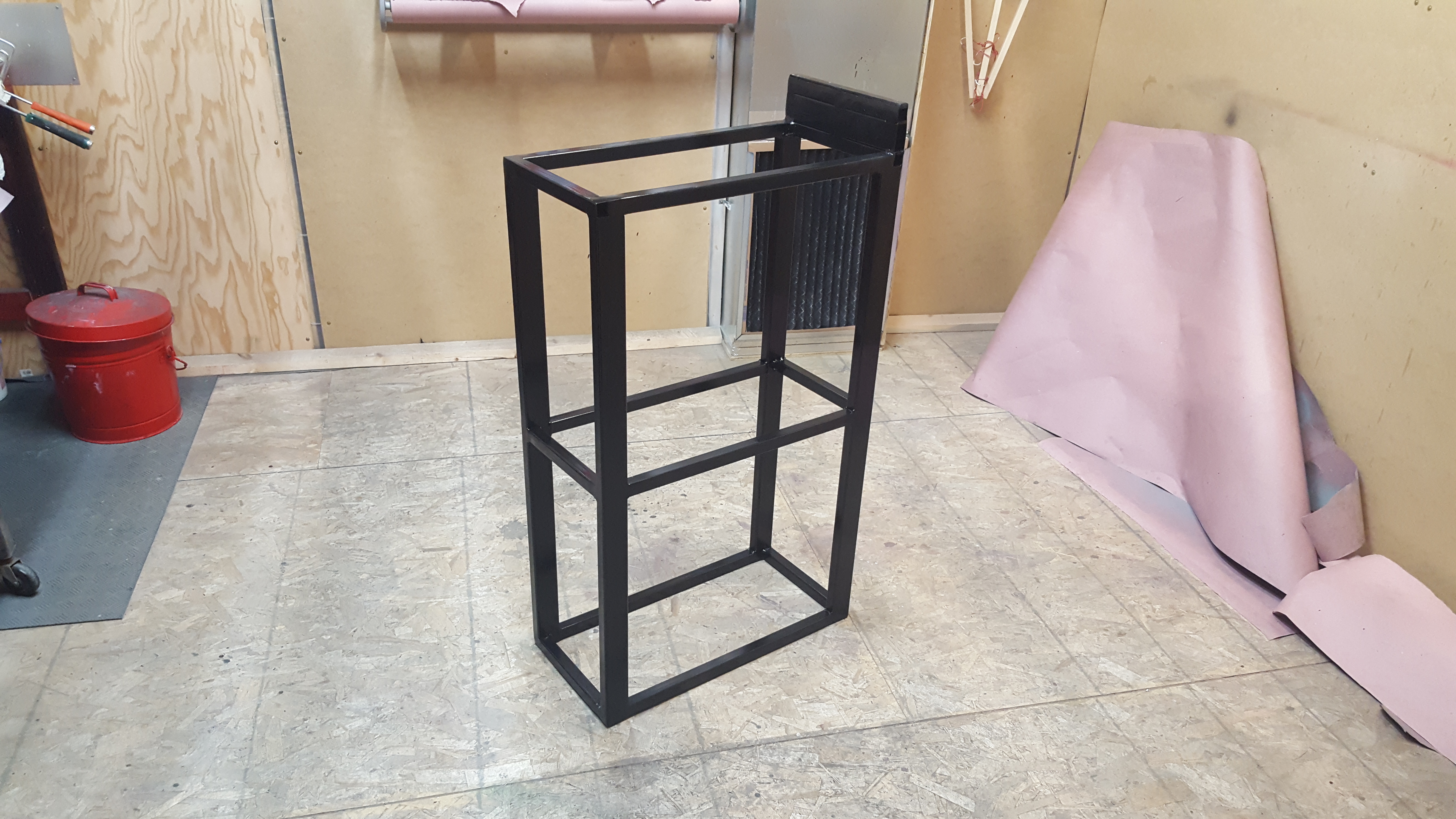
Painting
After welding I ground down all joints to be flush, partly for a cleaner look and partly to confirm that each joint had good penetration. I then used TC Maker’s relatively new painting room to apply a coat primer and enamel paint to help protect the frame over time.

Base
While building out the frame I also built a base for it using 1×2″ and 1″ square tubing that was designed to securely position the center of the plywood panels at about eye level of a person of average height. Using Fusion 360 I was able to locate the center of mass of the frame (with and without the panels attached) in order to optimally position the base. Even still, in hindsight I should have made the base just a little bit longer, or at least added some additional steel to spread the footprint out to make the piece feel more stable.
Also, this base should have been at least a foot or more shorter to make it easier for young people to interact with the piece. Even for adults the piece felt just a little bit too tall, and visitors needed to reach upwards to place pegs above their line of sight. It still ended up working OK, but I would do this slightly different if I had the chance today.
Lighting
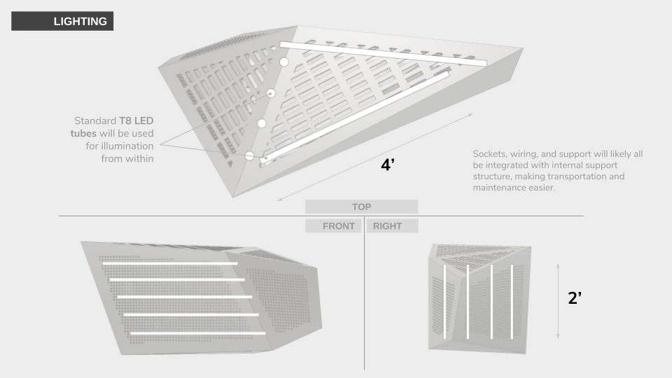
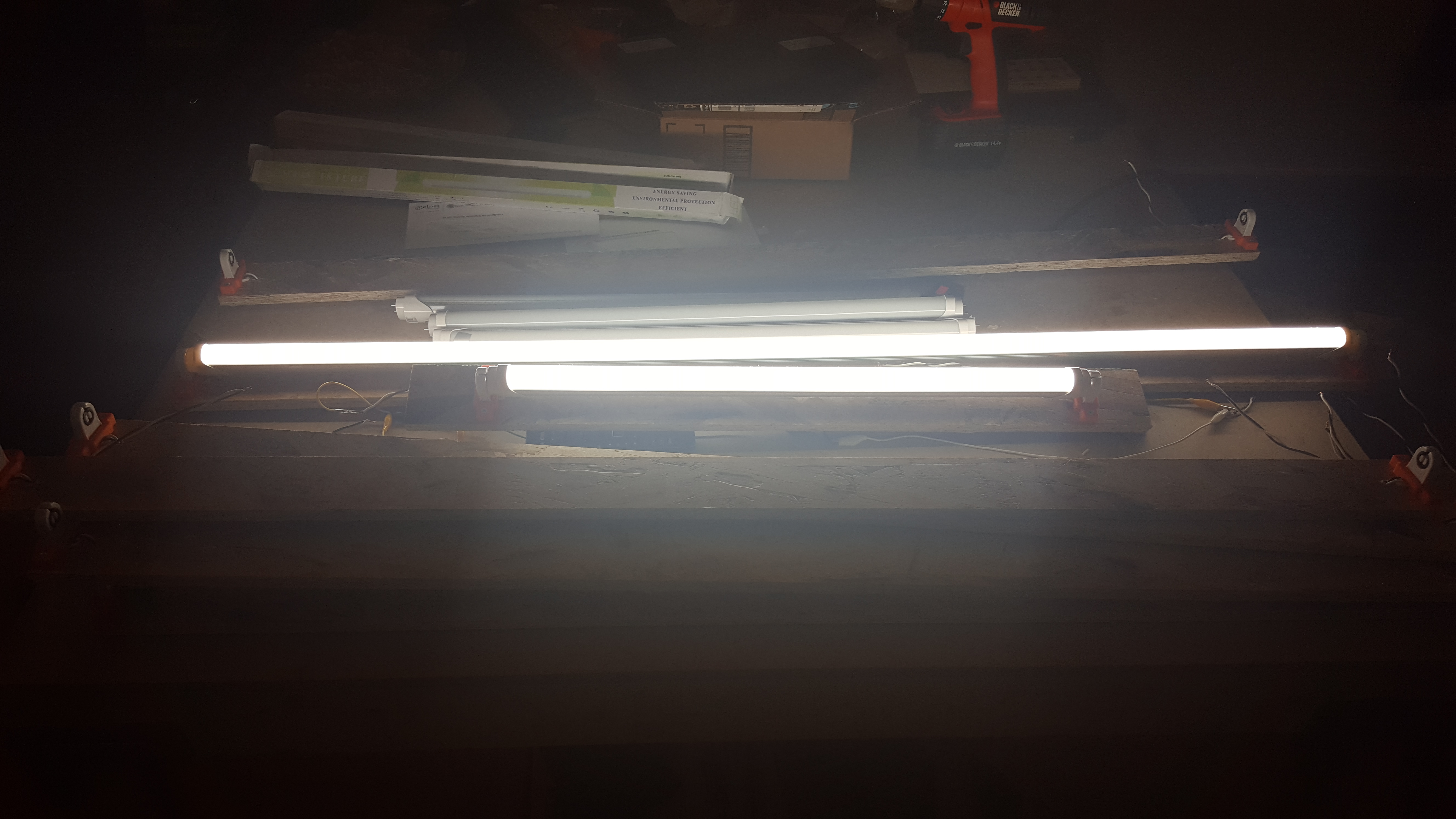
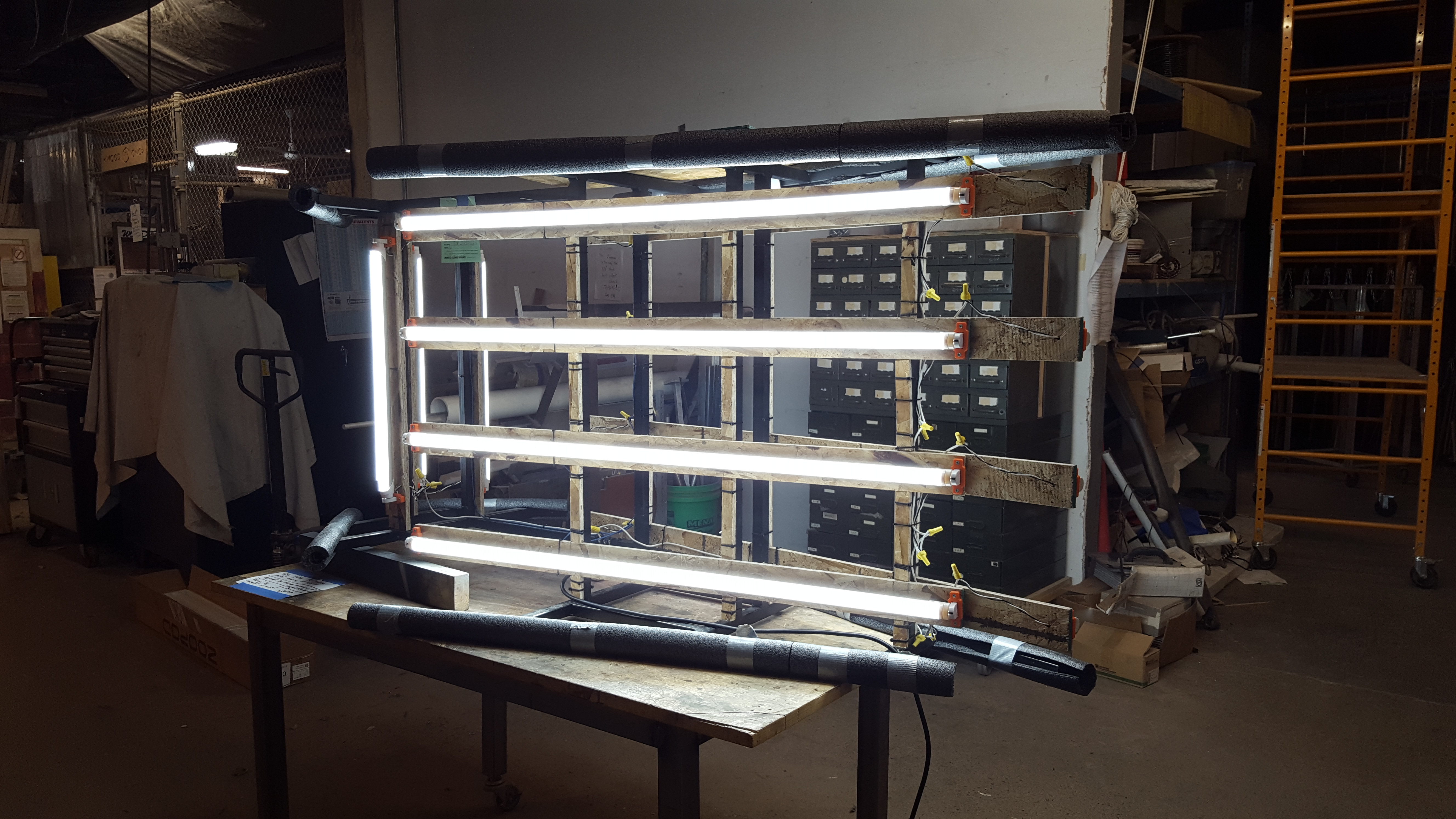
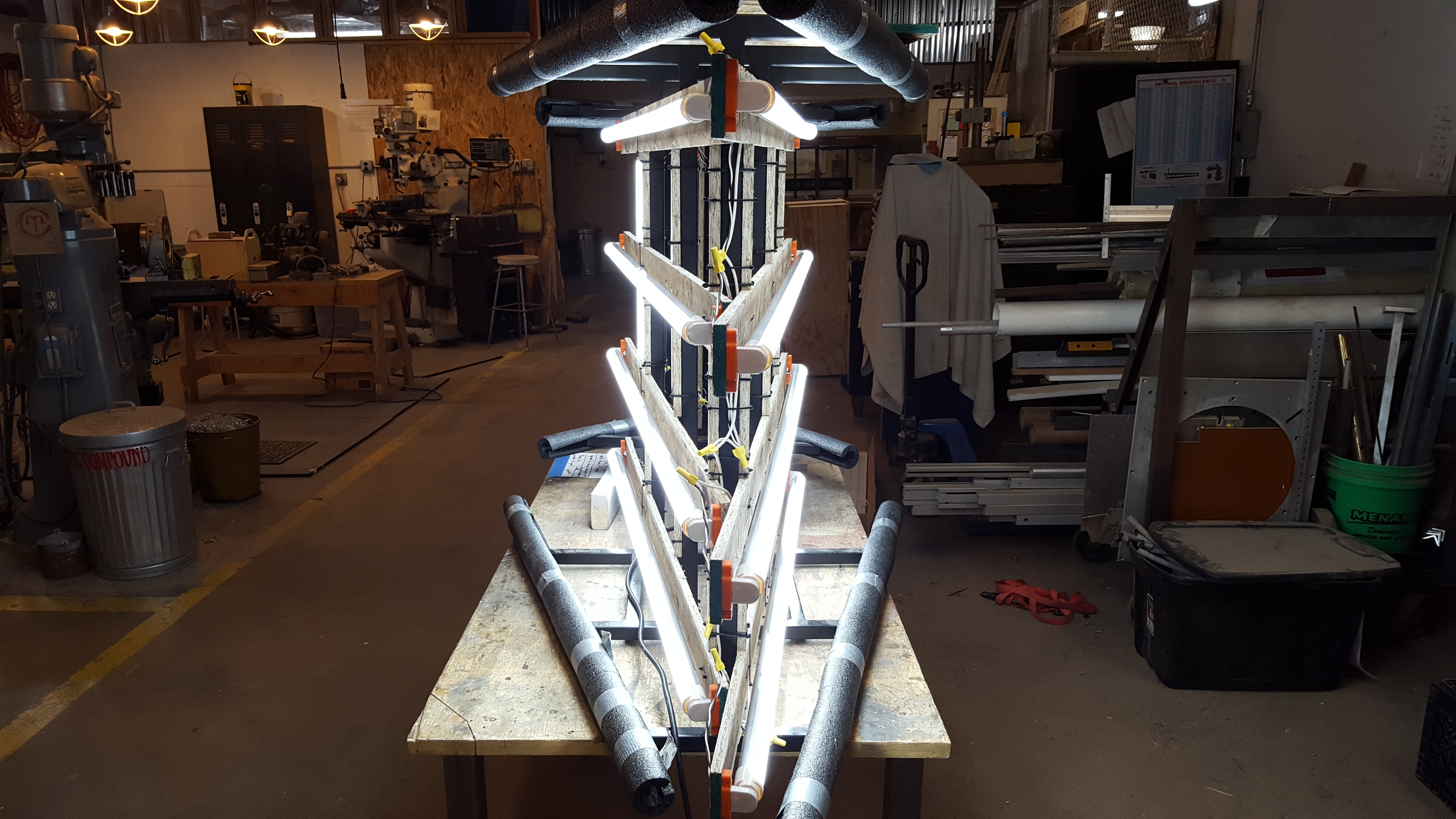
With the frame and base fabricated, painted, and assembled together, I then set about installing the custom lighting solution to illuminate all the pegs from within. I chose to use eight 4′ T8 LED bulbs (four per large panel) mounted horizontally, and four 2′ T8 LED bulbs (two per small panel) mounted vertically, all with a color temperature of 6500K.
Though their brightness was more than adequate, I feel like the lights could have used some additional diffusion to break up the relatively intense and obvious bands of light that were visible in the finished piece. Possibly some mylar or butcher paper sheeting could have done the job.
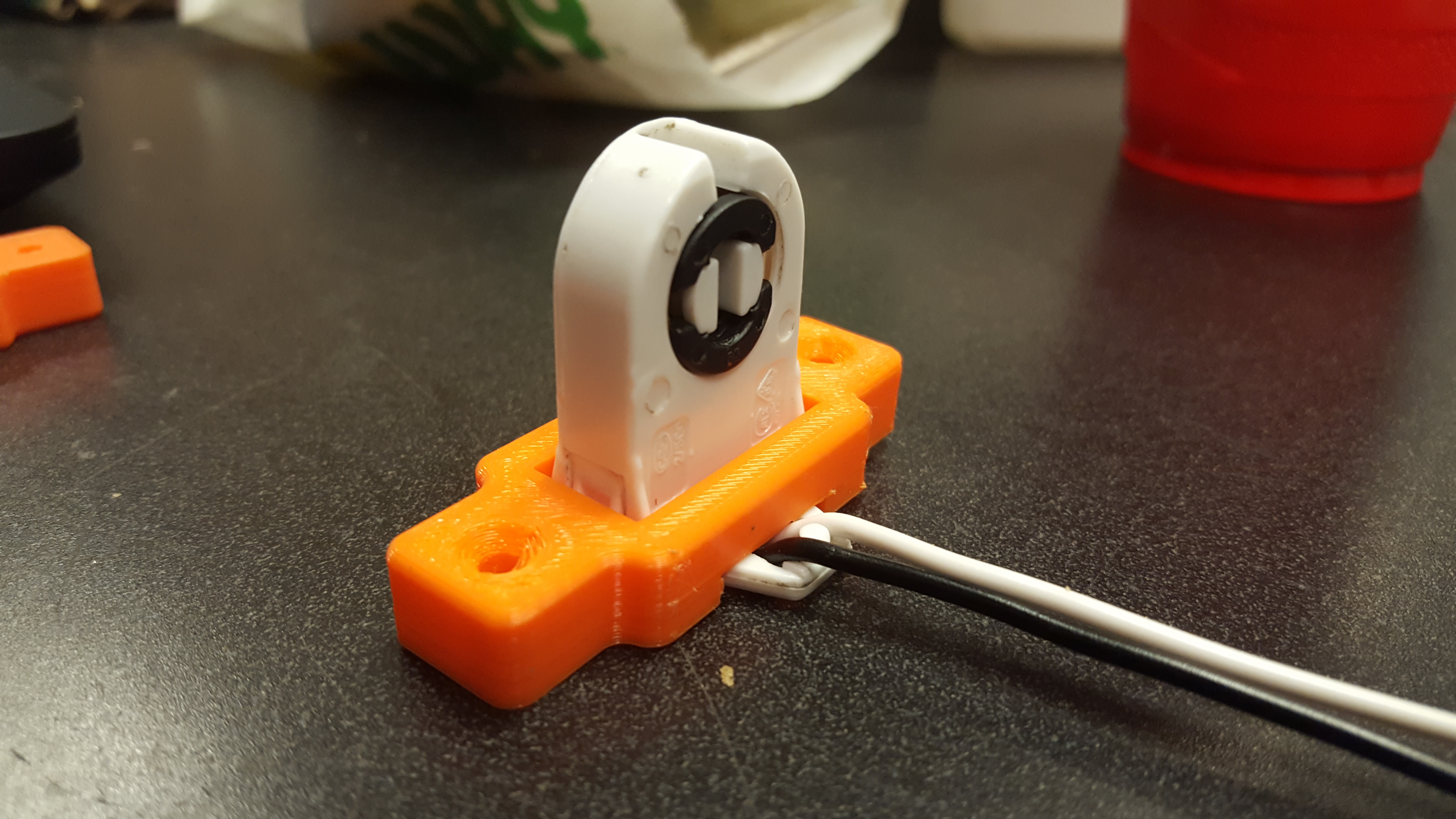
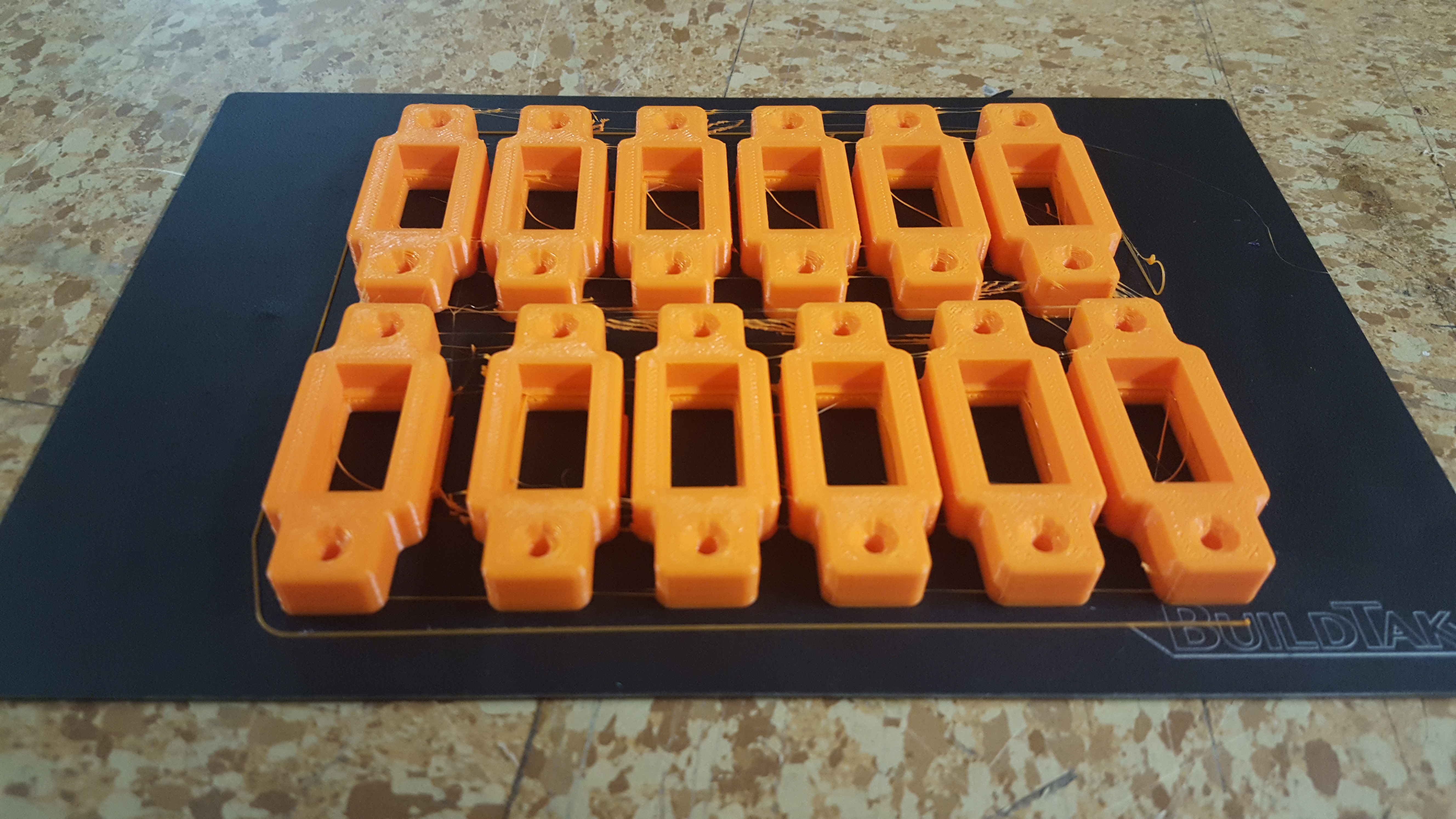
Custom 3D-printed fixtures
While sourcing parts for this section I quickly found that while bulbs are relatively cheap, commercial fixtures for them are often not, especially when you need a pile of single-bulb fixtures. The “sockets” for these bulbs (called “tombstones“), however, are very cheap, so it became pretty obvious to me that one could DIY custom fixtures using “replacement” tombstones and some scrap wood!
The only catch to this approach is that replacement tombstones are often designed to be mounted to thin sheet metal commonly found in commercial fixtures, and don’t “snap” into place the same way with thicker wood. To remedy this I designed some simple “adapters” for these tombstones that can be fastened to wood using traditional screws, which the tombstones securely “snap” into with a nice fit. I then printed a batch of these adapters using the 3D printer provided to the TC Maker hackerspace by Maker Rx for next to nothing in material costs.
Download the 3D model on Thingiverse

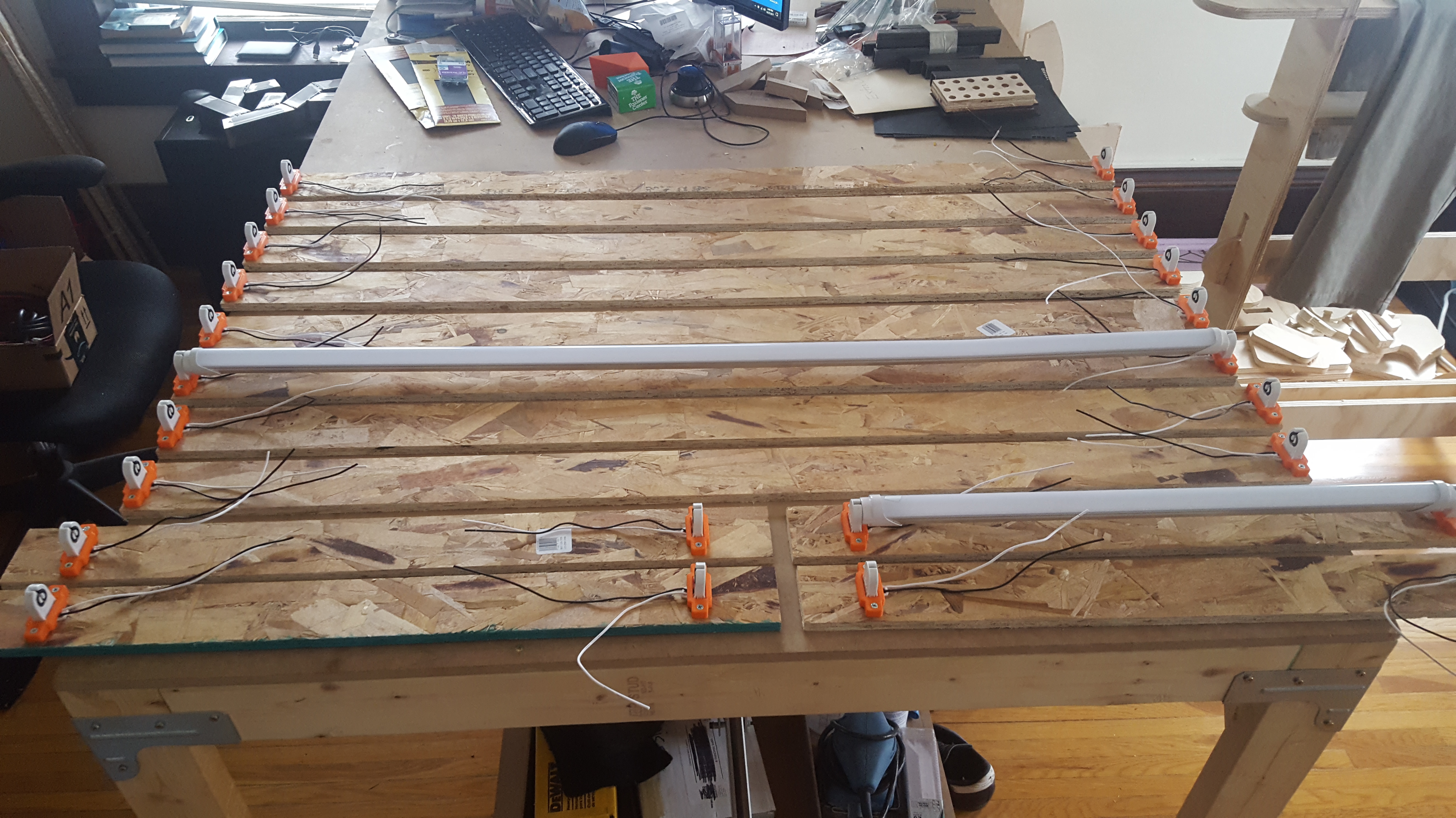
Assembly
With the tombstones and lights acquired, and the 3D-printed adapters printed, each of the DIY light fixtures could be assembled very quickly and without fuss. I tested each fixture and bulb at home before installing them in the steel frame.
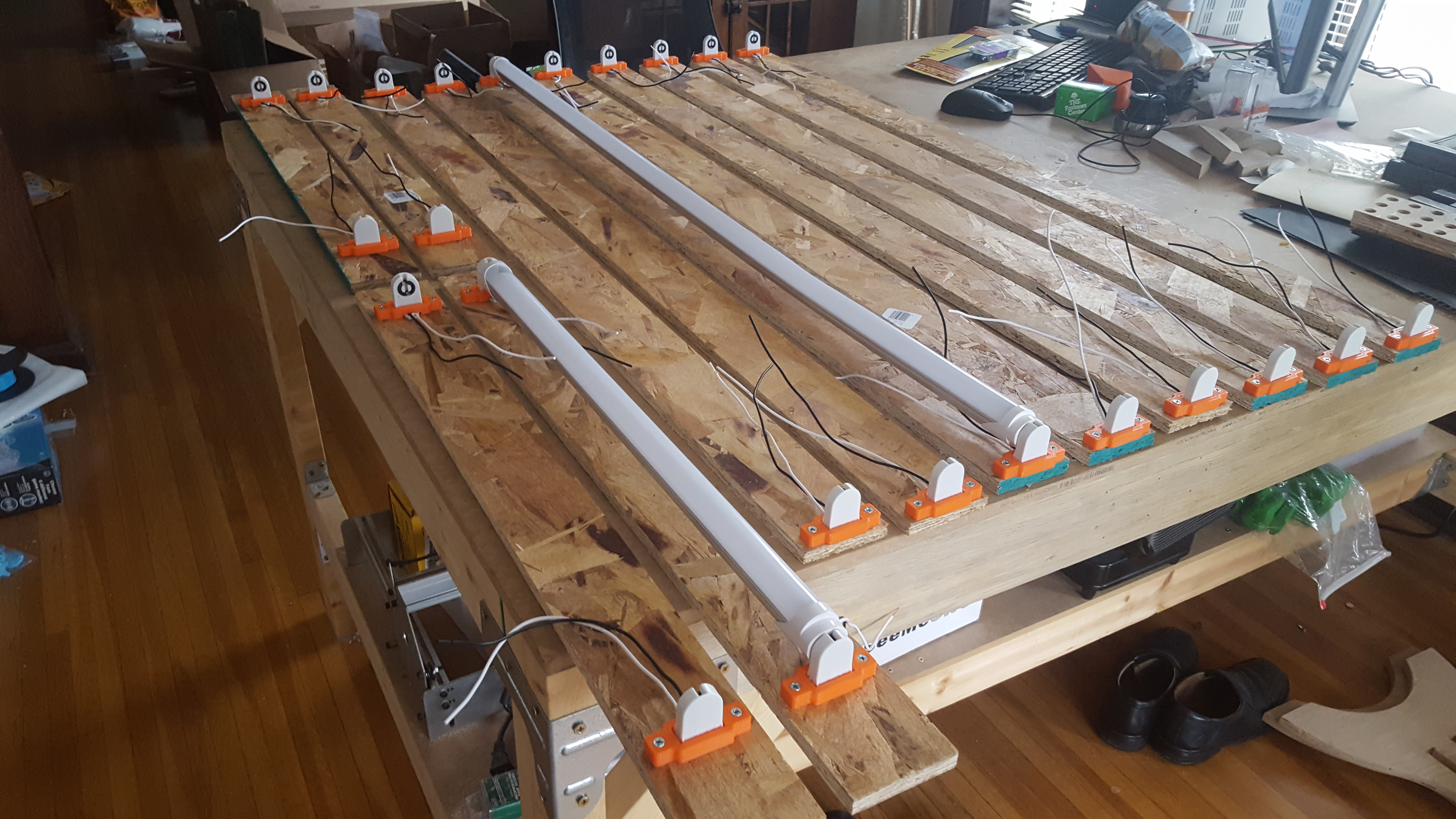
Installation and wiring
Each fixture was then installed onto the steel frame using wood spacing shims and zip ties. Next, all of the fixtures were wired up in parallel using wire nuts for easier maintenance in the future, then wired to a common terminal block that was also connected to a grounded AC power cord for the gallery to plug in to any nearby outlet.
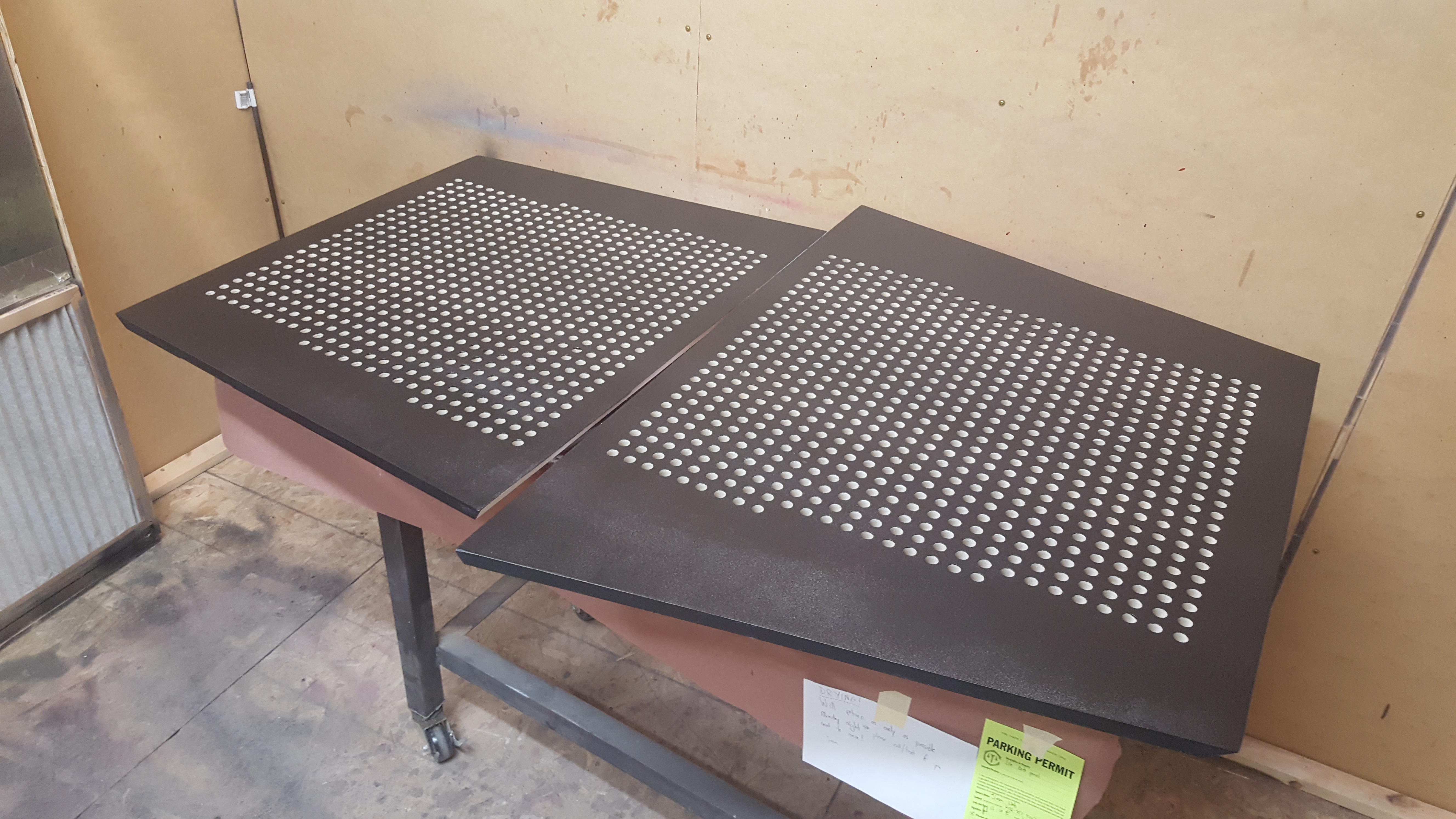
Panels
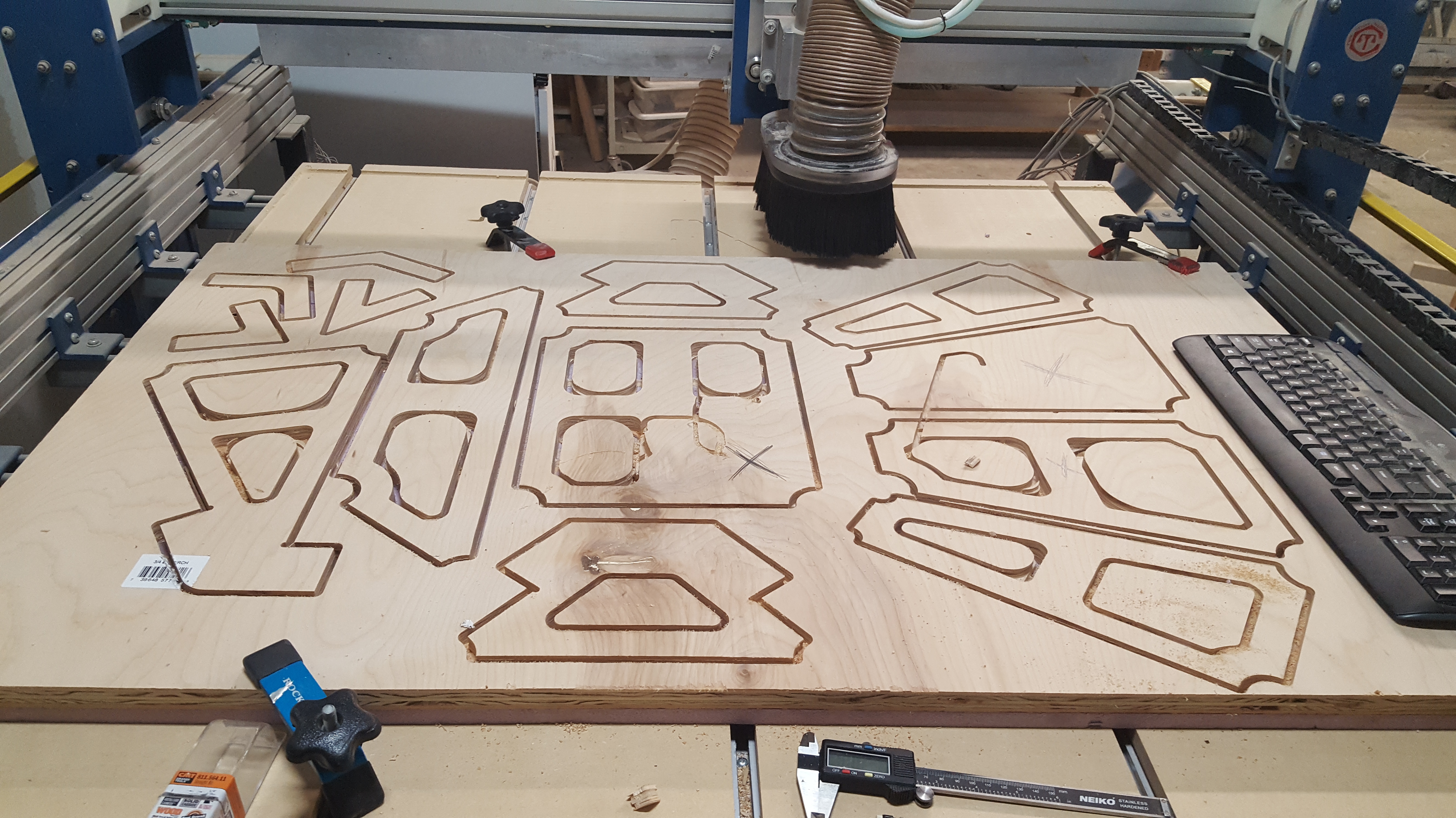
Each of the wooden panels that form the outer “shell” of the piece were creating using a CNC router, which in some ways made this step somewhat easier than the rest of the project. Very little manual labor was required to create them, though some effort was certainly spent on the preparation and optimization of the designs for the machine itself.
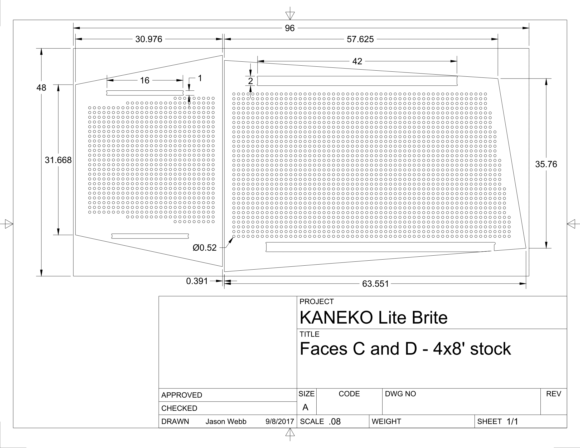
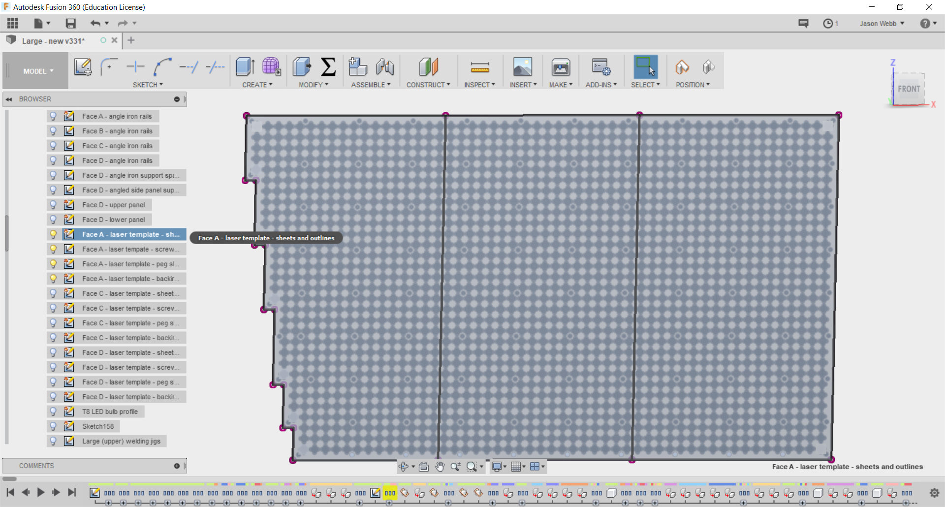
Designs for fabrication
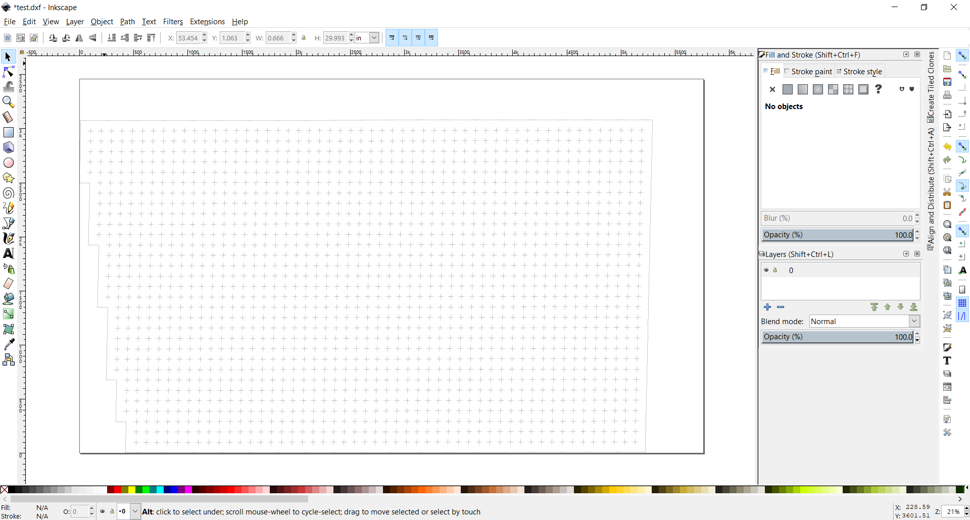
In order to fabricate these panels, instructions (called “toolpaths”) for the CNC router must be created – much like a computer program or script for the machine to follow line-by-line. Although Fusion 360 has the ability to generate toolpaths (through the built-in CAM workspace) for each panel directly from the complete 3D model itself, I felt it was better to “flatten” all the panels into 2D designs so that they could be efficiently arranged onto full 4x8ft stock sheets (see drawings below).
Fusion 360 makes it easy to export 2D design files (DXFs) from my arranged sheet designs that any CNC router operator could open in their CAM package of choice. It also provides the ability to create really helpful technical drawings with dimensions and annotations to make it clear to the fabricator what is expected. Best of all, all of the features I’ve mentioned are driven by the original 3D model in real time! This means that any time I wanted to update something like the diameter of the holes, I only had to change it in the 3D model and all the toolpaths, stock sheet assemblies, and technical drawings would automatically reflect the the change. Amazing!
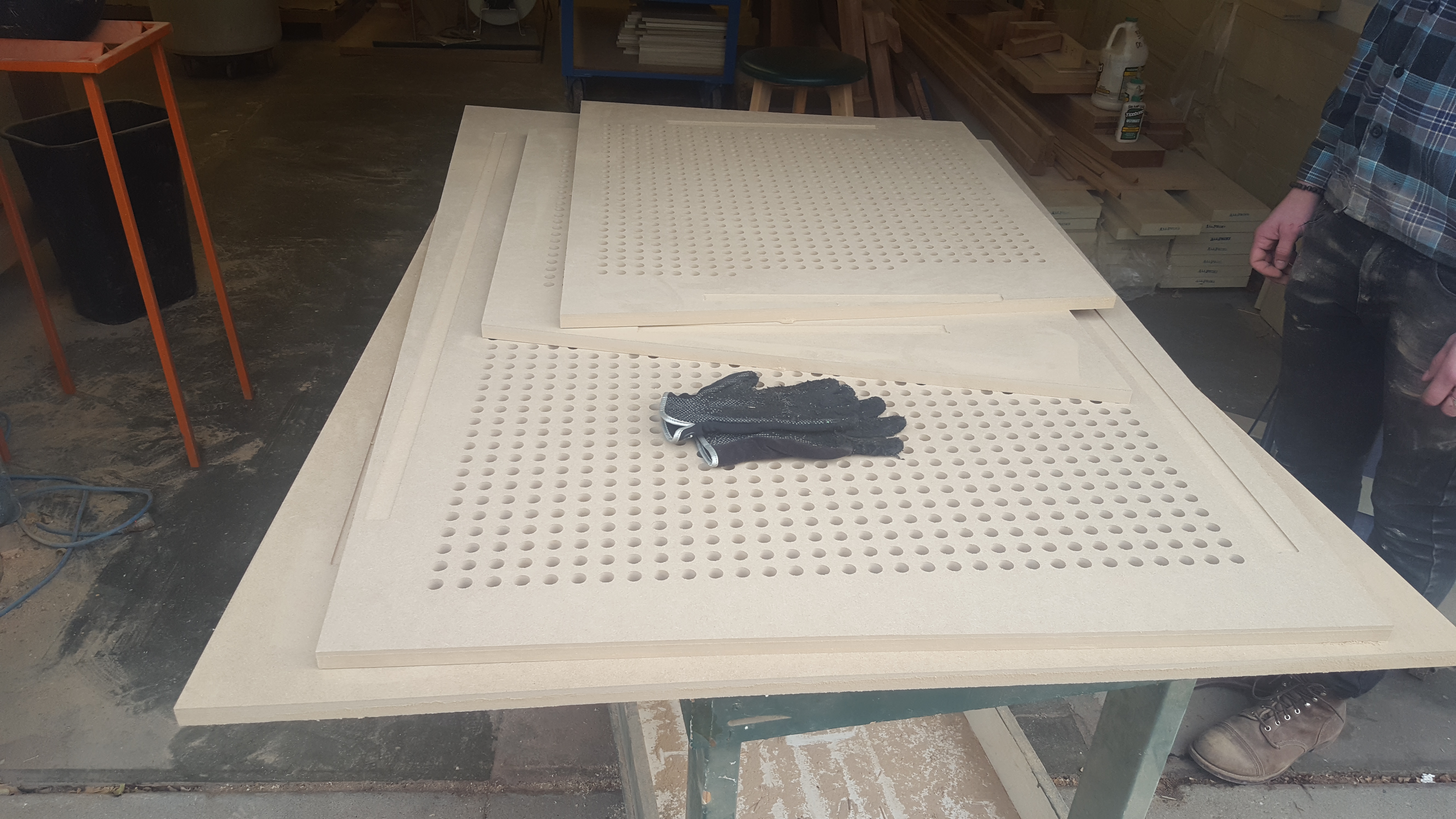
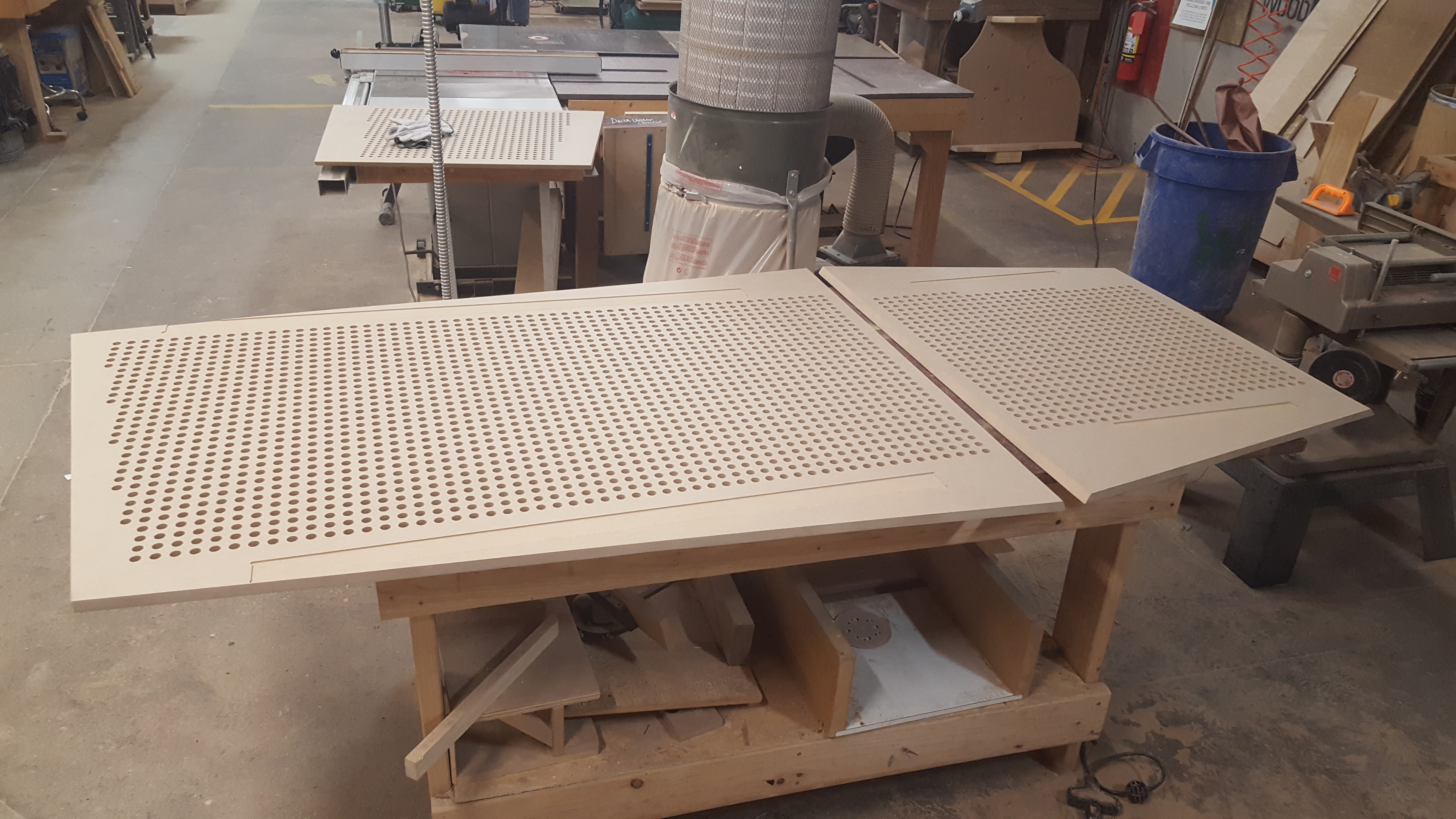
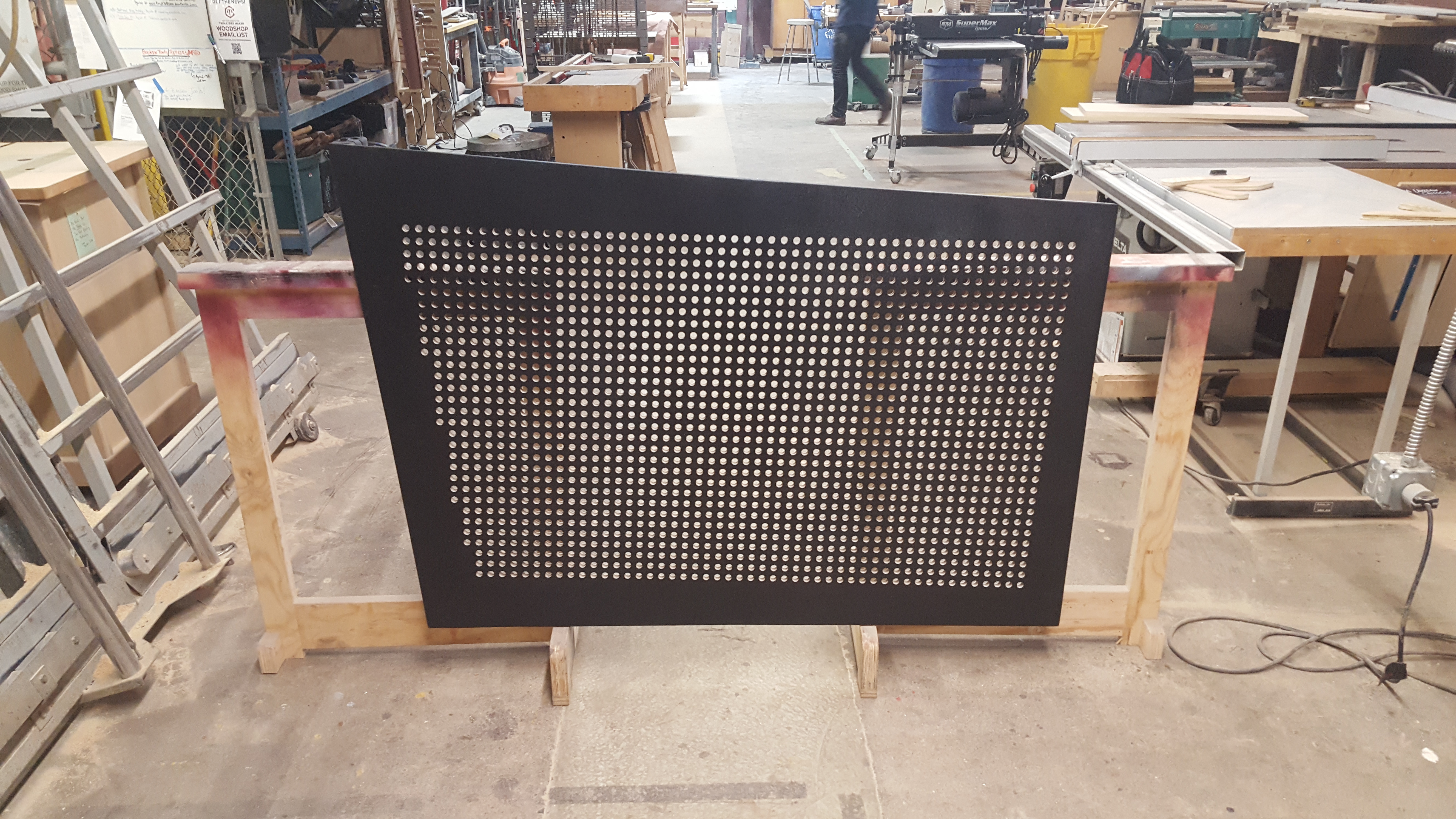
CNC fabrication
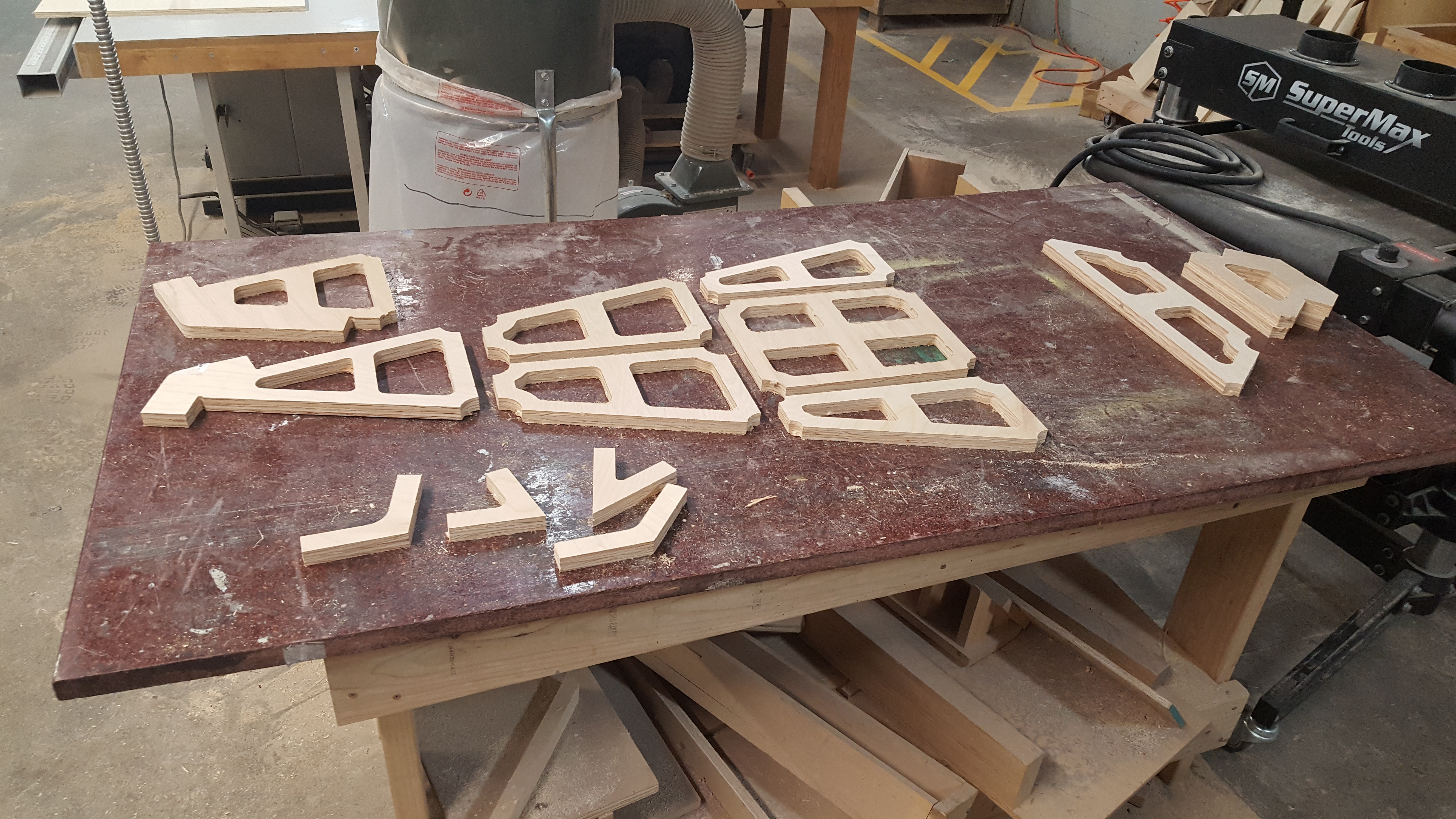
With designs in hand I headed over to American Workshop, a local community woodworking shop, and worked closely with it’s owner Reed Wilkerson to carve each of the panels out on their in-house 5x8ft CNC router. We spent some time discussing end mill selections, toolpathing strategies, workholding, and more, even going so far as to many some test cuts to make sure that the finish looked good and the acrylic rods I wanted to use as pegs would comfortably slide in and out.
After one or two test runs, Reed was eventually able to dial in the machine and CAM software settings in order to produce panels that required almost no post-processing straight off the machine! This process ended up taking a little longer than I was hoping for, but nonetheless I had a great time working with Reed, and would not hesitate to recommend American Workshop for anyone looking for a community-oriented woodworking shop in the Minneapolis area!

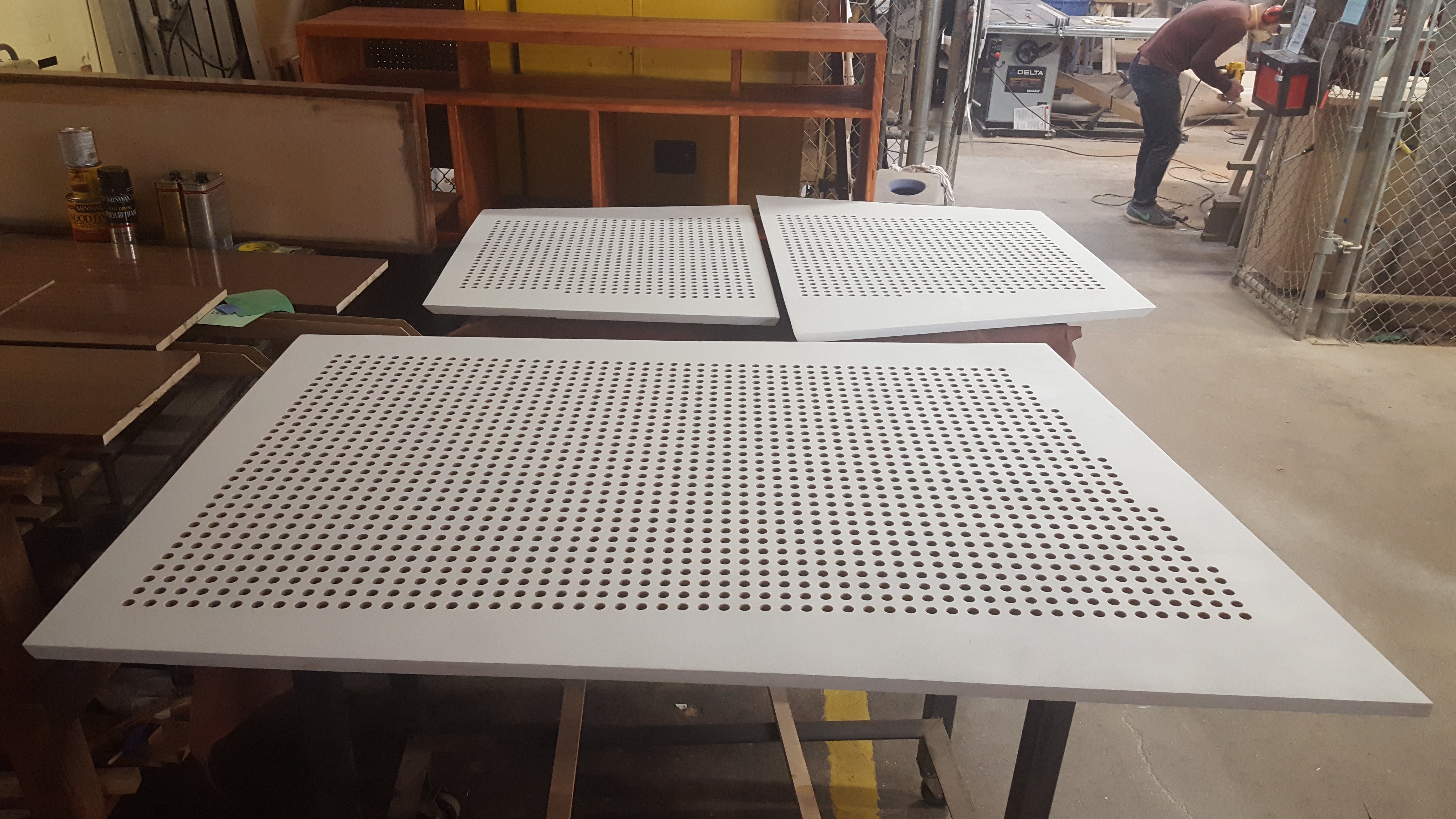
Painting
Back at the TC Maker hackerspace I carefully sanded each of the panels, applied primer, then painted their outer faces using a high-gloss enamel paint. Originally I intended for this to end up with a mirror-like reflective surface, but I found out quickly that achieving such a finish is much less about the paint itself and much more about the painstaking, laborious process of sanding the wood and primer with increasingly fine sandpaper.
I put as much energy as I could into process, but ultimately had to move forward and get a final coat applied in time for adequate drying to take place. Though the finish was not mirror-like by any stretch of the imagination, there did end up being a really interesting, subtle, and tactile texture coming through that I was much happier with than I was expecting. Sometimes you’ve just go to roll with it!
Mounting system
Once the panels had all been painted and left to dry for a little while, I then needed to install the angle irons I prepared earlier so that each panel could be hung and secured to the steel frame. I opted to use both “Liquid Nails” construction adhesive and short wood screws to secure these mounts to the panels to make extra sure that they could handle the weight and wear-and-tear over time.


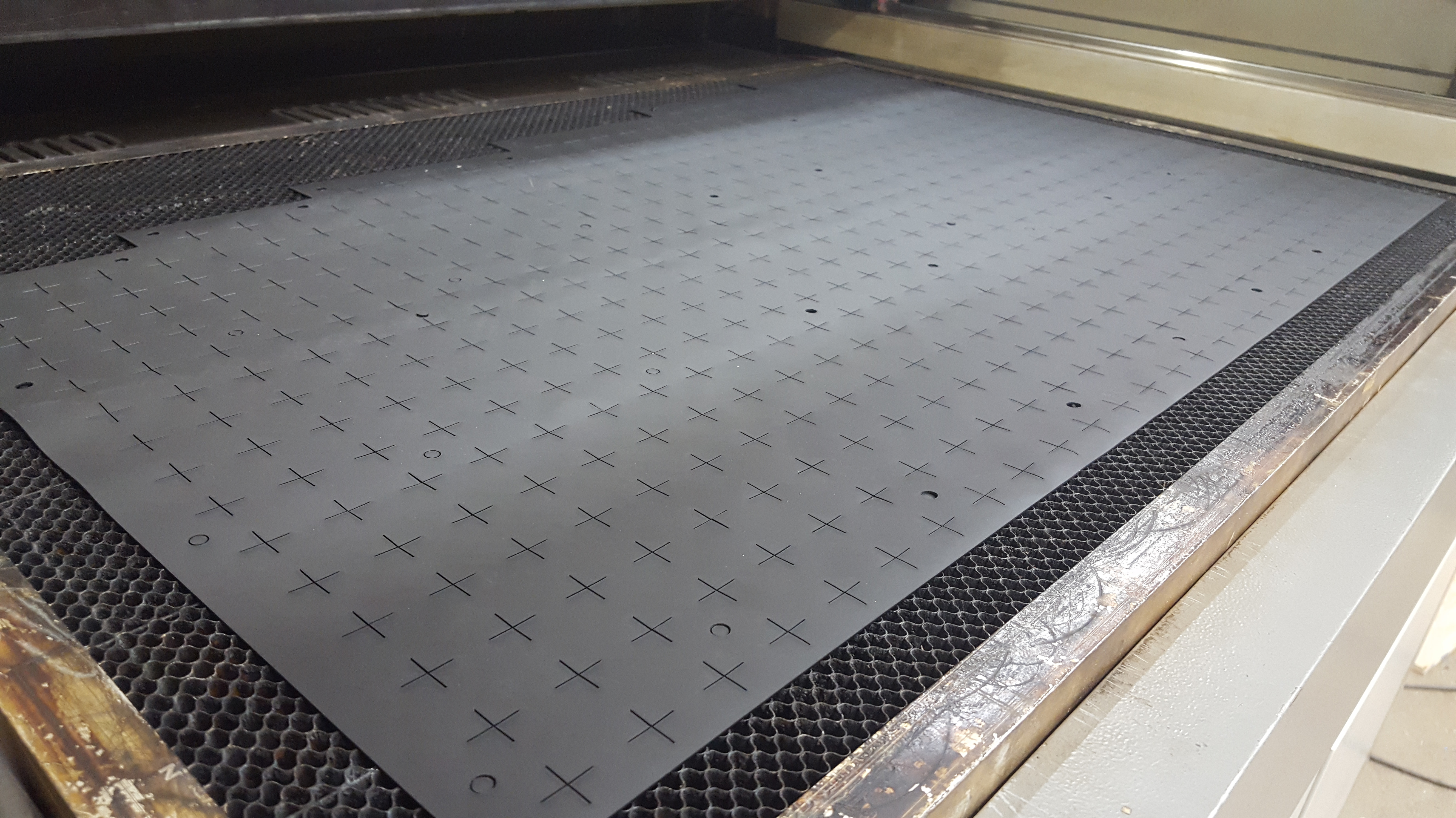
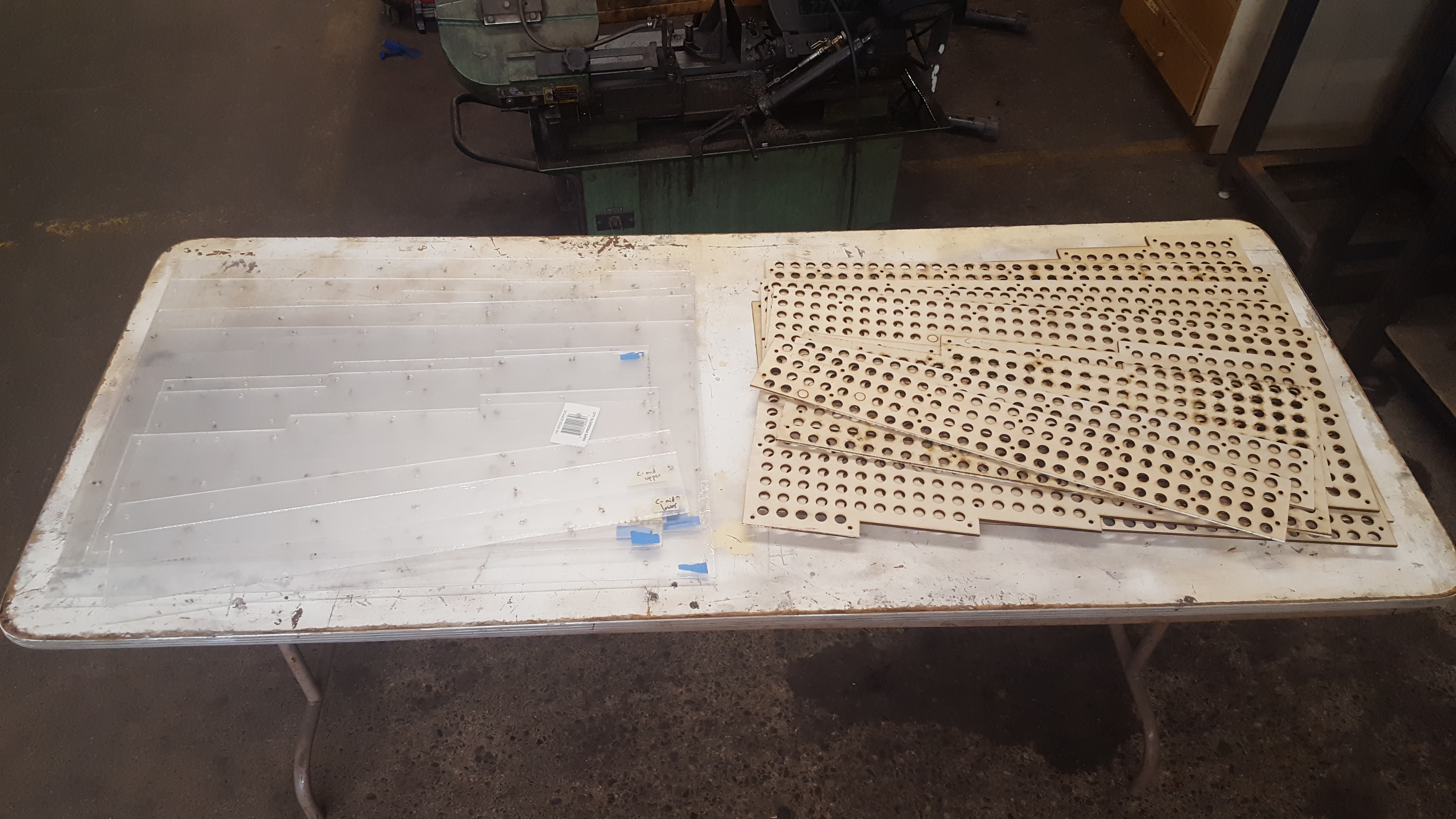
Fabrication and installation of baffle layers
Finally, I laser-cut all of the layers of materials needed to construct the baffles that block most of the light coming from within the piece until pegs were inserted. As described earlier, this system would consist of Santoprene rubber (1/32″ thickness), thin plywood (1/4″ thickness), and plexiglass, all of which with different patterns of holes and lines laser-cut into them.
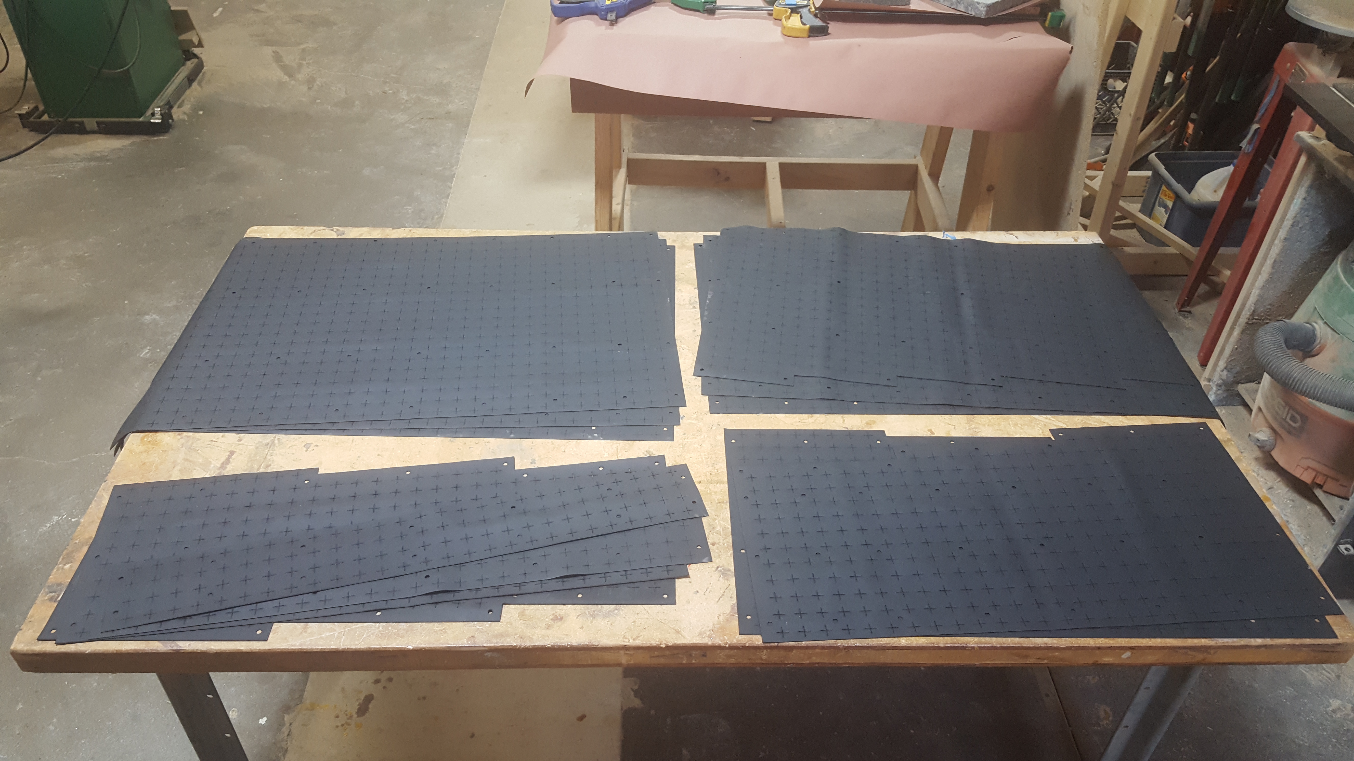
For this task I used the 2×3′ ~60W laser cutter over at the TC Maker hackerspace, which made short work of the designs I created. Though there were many thousands of cuts to be made, the designs were very easy to create using Fusion 360 using projected 2D sketches of each panel, exported as DXFs.
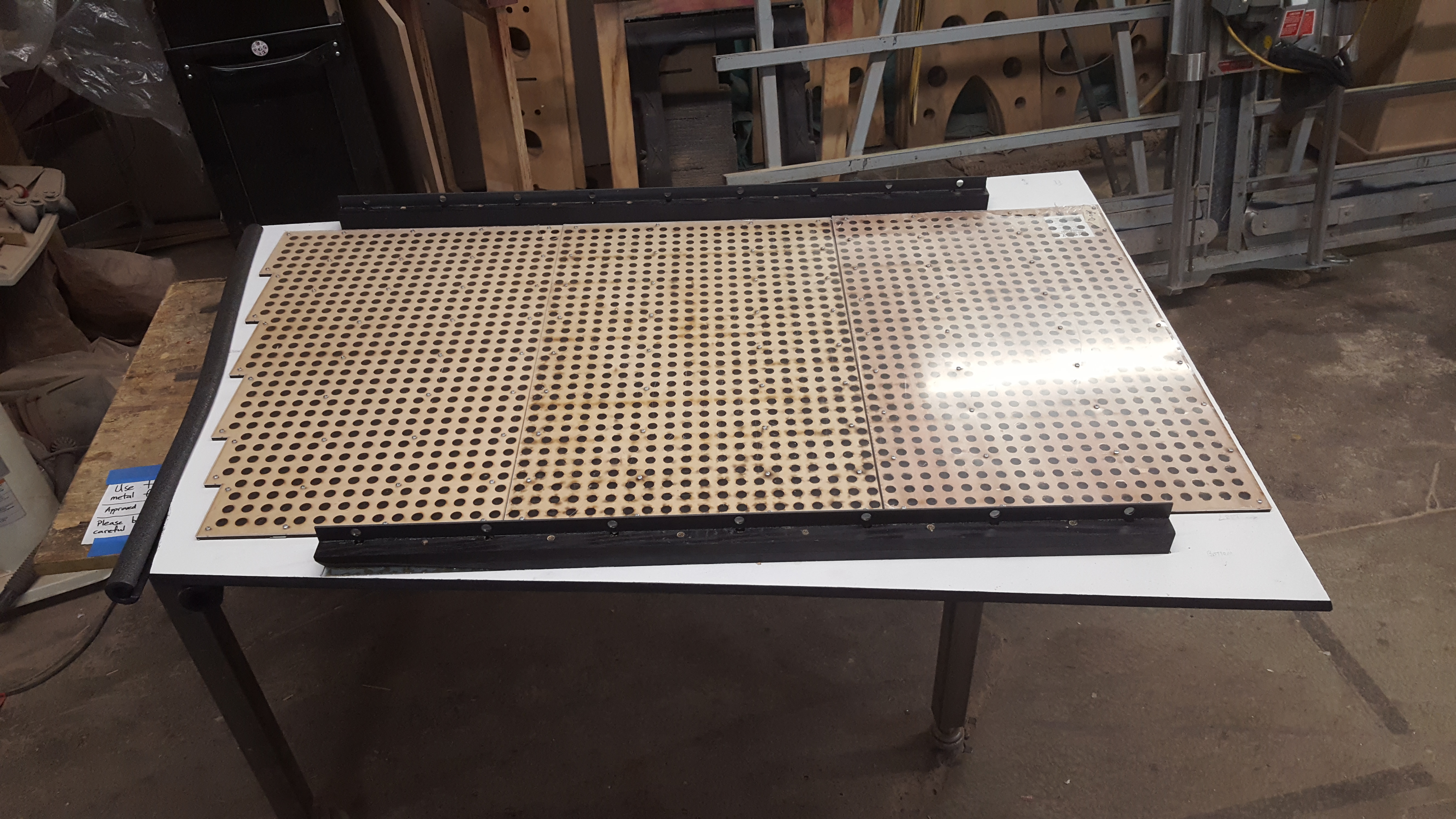
After laser cutting each layer, I carefully placed and aligned them onto the backs of each panel, using short wood screws to hold them all together and keep them securely fastened to the panels. I opted not to use any glue at this stage so that the baffles could be easily disassembled in the future and any of it’s layers replaced after they have been worn down from use (particularly the rubber sheets – they aren’t indestructible!).


Pegs
The final part of this project to fabricate was by no means the easiest, though I did expect it to much easier when I was doing the initial planning. It wouldn’t be a Lite Brite without lots of colorful plastic pegs for the visitors to insert into the panels and build designs with! In this case, “lots” means over 4,600 of them, each measuring 1/2″ in diameter and 2″ long.
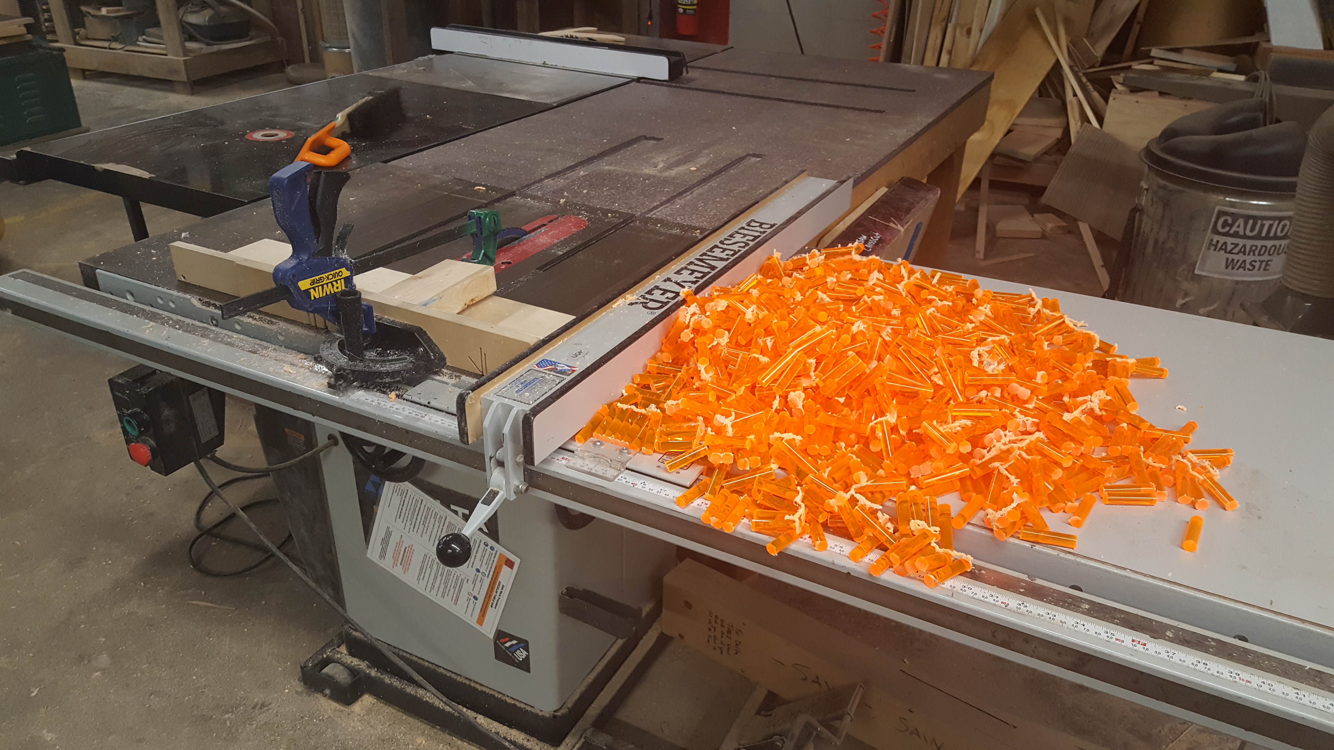
Very early on in this project I sourced some fluorescent acrylic rods from a local dealer (A-1 Acrylics) and ran some tests using TC Maker’s laser cutter. I was initially able to achieve consistent, high-quality cuts with it, and felt very confident about being about to scale up and cut large amounts of pegs by filling up the machine’s bed with rods on a custom spacing jig. Unfortunately, the more I cut the worse the cut quality got, eventually forcing me to abandon laser cutting altogether in favor of a more hands-on process. It’s possible that the acrylic fumes and residue were building up on the optics assembly of the laser cutter, resulting in progressively less effective power over time.
Instead I had to resort to using a table saw with a plastic-cutting blade to laboriously cut pegs one at a time by hand. Using a crosscut sled, I tried cutting bundles of 3-6 rods at once to increase the yield of each cut, but found that the cuts weren’t as clean and would often end up with very large, bubbly burrs caused by the build up of molten plastic dust attaching to the rods during the cut. Eventually I learned I had to cut every single peg one-by-one, as well as re-cut all of the previously-cut pegs to give them a clean edge. All in all this process took about 40 hours of standing in front a table saw, but the result was worth it!

Assembly
With all of the various sub-systems fabricated and looking good, I could then do an assembly test of the entire piece to make sure that all the hard working and planning I had done to this point was solid. All that really needed to be done was for each of the four outer panels to be hung onto their respective railings on the steel frame, then fastened using 1/4″ lag bolts and nuts. Once assembled I found the piece to be very stable and well-balanced, with all of the seams joining together nicely.
Along with some friends at the hackerspace, I created a few test designs using the acrylic pegs in various parts of all four panels to ensure a consistent feel and quality. We were all very happy with the tactile feeling it had, and with how well the pegs were gripped by the rubber once inserted. Overall, it was a complete success!
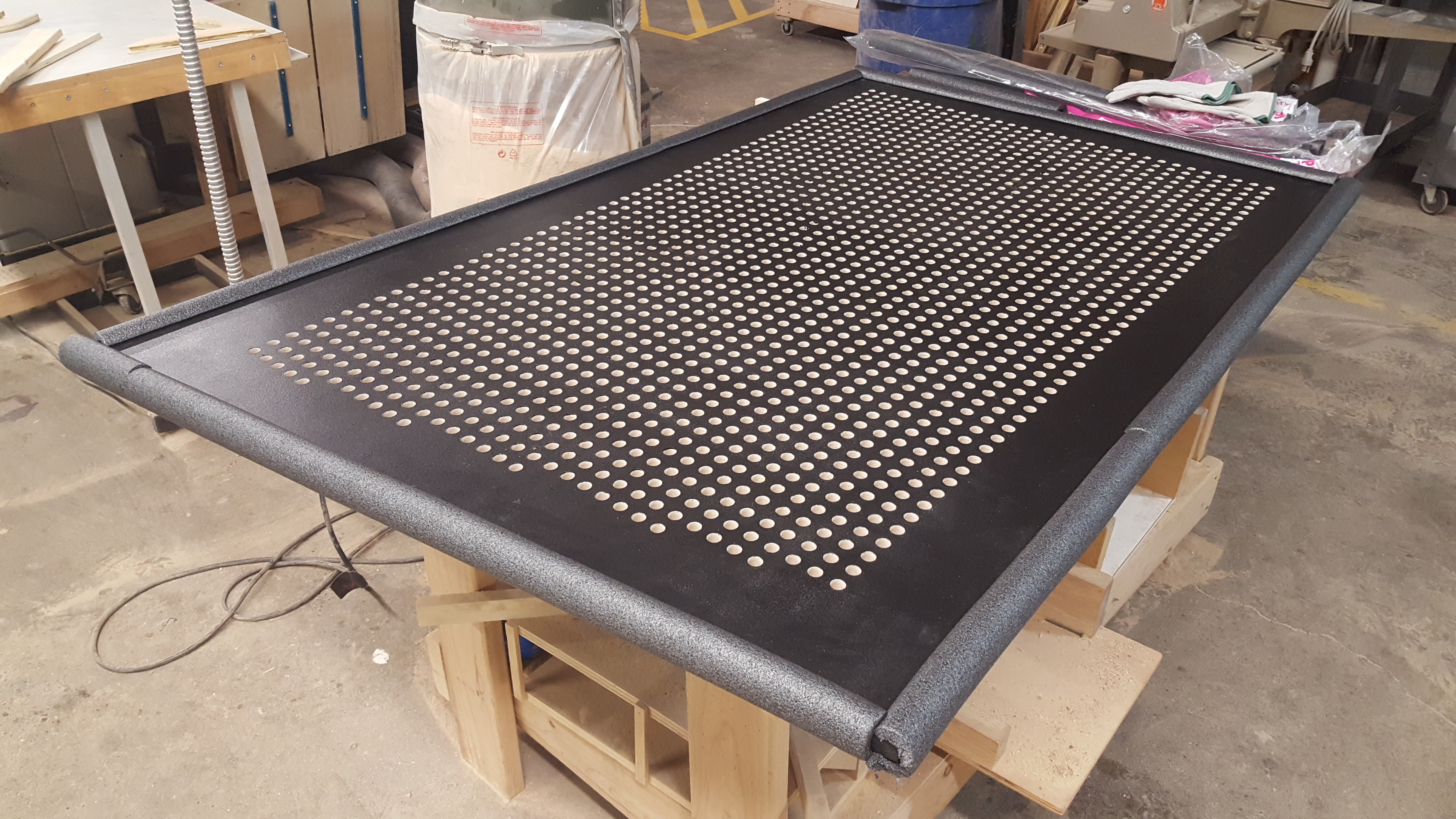
Delivery
Finally it was time to prepare the piece for transport and get it to KANEKO for the exhibition! Luckily I thought this step through during the design and planning phase early on, so all I had to really do was stick to the plan!
I removed each of the four outer panels and stacked them in a U-Haul trailer using foam tubes as spacers, ratcheting the stack down securely using straps. Next I disconnected the steel frame and base assemblies and loaded them onto my truck, strapping them down as well. The drive from Minneapolis to Omaha was long, but went off without a problem.
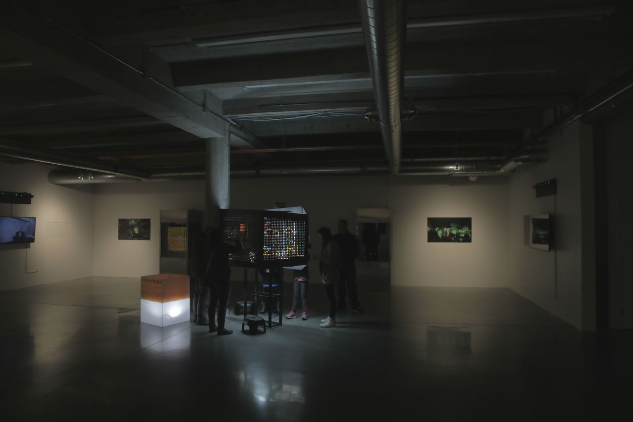
On site at KANEKO I re-assembled the piece over the course of a few hours, then worked with the staff to find a good staging location for it for the show. It was so gratifying to see how excited everyone was to have it in the gallery, and I couldn’t be happier with how it all ended up!