Lumiboard (rev B) prototypes and testing: board updates, firmware, LED testing and Bluetooth
For the past few months I have been working hard on a project I started quite a while ago to make it easier for me to work with different kinds of LEDs and control them in a variety of ways. I’ve just finished testing out the second revision of this board, which I am calling Lumiboard, and am about to start prototyping the third version.
Lumiboard is a small, open-source circuit board designed to make it easy to connect to and control nearly any kind of LED available, from low-power discrete LEDs, to high-power RGB LEDs, WS2812 LEDs (NeoPixels) and even I2C devices. What makes it really fun for me is all of the extra bits I’ve added to make it easier to interact with the LEDs. You can connect three potentiometers to have direct control over the RGB values of the LEDs, or connect an external sensor board (being prototyped now) with temperature, audio and ambient light sensors. There is also a footprint for a common HC-05 / HM-10 Bluetooth transciever so you can control your LEDs from a smartphone or tablet!
I originally started working on this board for fun, but have recently found that it would be perfect for some other work I am doing right now, such as collaborating with glass artist Kenny Galusha. Kenny and I are working hard on a Kickstarter to make our work available, so you will be able to get your own Lumiboard and/or glass artwork very soon!
Schematic and board design
There have been a lot of big updates to the board design, as I have learned quite a lot since the first version. I’m very proud of how far I’ve come in just a year when it comes to PCB design, just compare this version with the previous one!
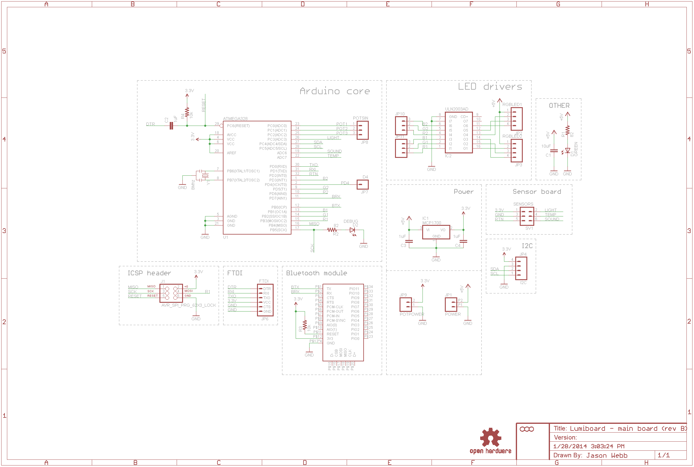
All of the board design files, firmware and bills of materials are available at the project’s official Github repo here:

List of updates for revision B
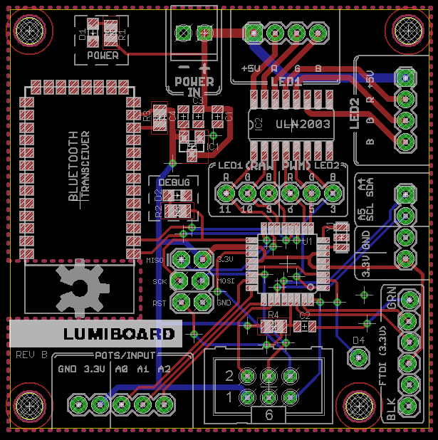
I’ve made a number of big updates to the board design, most important of which is moving away from finicky DIY interconnects to much more friendly screw terminals. They are slightly more expensive, but I now feel that they are a key selling point of the board – now it feels more like a prototyping platform. Here are all of the updates for the Revision B design:
- Screw terminals instead of male headers – this makes it much easier to connect components to the board without special interconnects.
- Added 6-pin ICSP interface so that bootloaders can be flashed onto the ATMega328 easier.
- Added six male headers between the ATMega328 and the ULN2003 so users can tap into the raw PWM signals directly, instead of being forced to sink LEDs through the ULN2003.
- Added 3.3V and GND access next to the I2C interface (SDA/SCL pins) to make it easier to setup a common I2C power bus.
- Added a single floating header that breaks out the D4 pin so you can access it, thus making every single pin of the ATMega328 accessible!
- Enlarged the overall board footprint to accommodate the screw terminals and additional connections.
Firmware development and plans
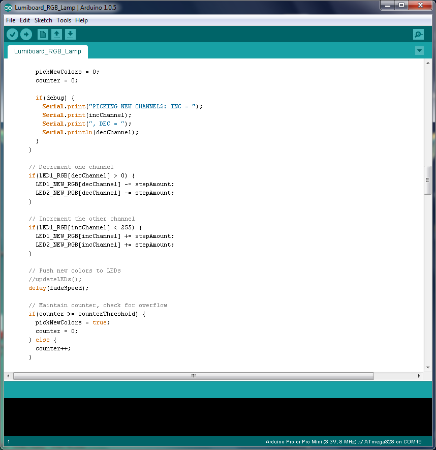 To make the board accessible to future users, I’ve been working on a comprehensive sketch to cover many kinds of lighting modes and scenarios. The goal is to show off every function of the board by letting users choose between different operating modes that flash the lights in different ways.
To make the code less intimidating (and more easy to port to a library in the future), I’m trying to decouple all of the hardware-related code (flipping pins, buffering inputs, etc.) from the actual behavior of the LEDs. The hope is that the user can provide some sort of arbitrary pattern for the lights to follow and simply turn on or off any of the connected LEDs without having to recompile and reupload code. Eventually this kind of control will be available via the on-board Bluetooth transciever connected to a smartphone or tablet.
Right now I’ve written and tested the following functionality in the code:
- “Color wash” mode – creates beautiful and randomly-cycling colors
- Control the LEDs’ RGB values using three potentiometers.
- “Reactive nightlight” mode – adjusts brightness of LEDs based on ambient light level in the room using external sensor.
- Global control of LED RGB values, with a brightness buffer so that sensors can modulate the current LED colors at any time.
- Early “party mode” – pulses the LEDs based on input from an external audio sensor.
In future updates I plan on adding the following functionality (and then some):
- Support for more types of LEDs. Right now I’m just using two 3W RGB LEDs, but I’d like to support individual single-color LEDs, Adafruit’s NeoPixels/WS2812s and the BlinkM.
- Integrate data from an external sensor board (prototypes being fabbed right now) that contains a temperature sensor, ambient light sensor and microphone preamp circuit.
- Further decouple the sensor interactivity from the LED behavior. In other words, make the audio sensor modulate the LEDs no matter what animation is playing.
- Add a very simple sequencer, much like the BlinkM’s, to let the user make pre-programmed patterns.
Testing 3W RGB LEDs
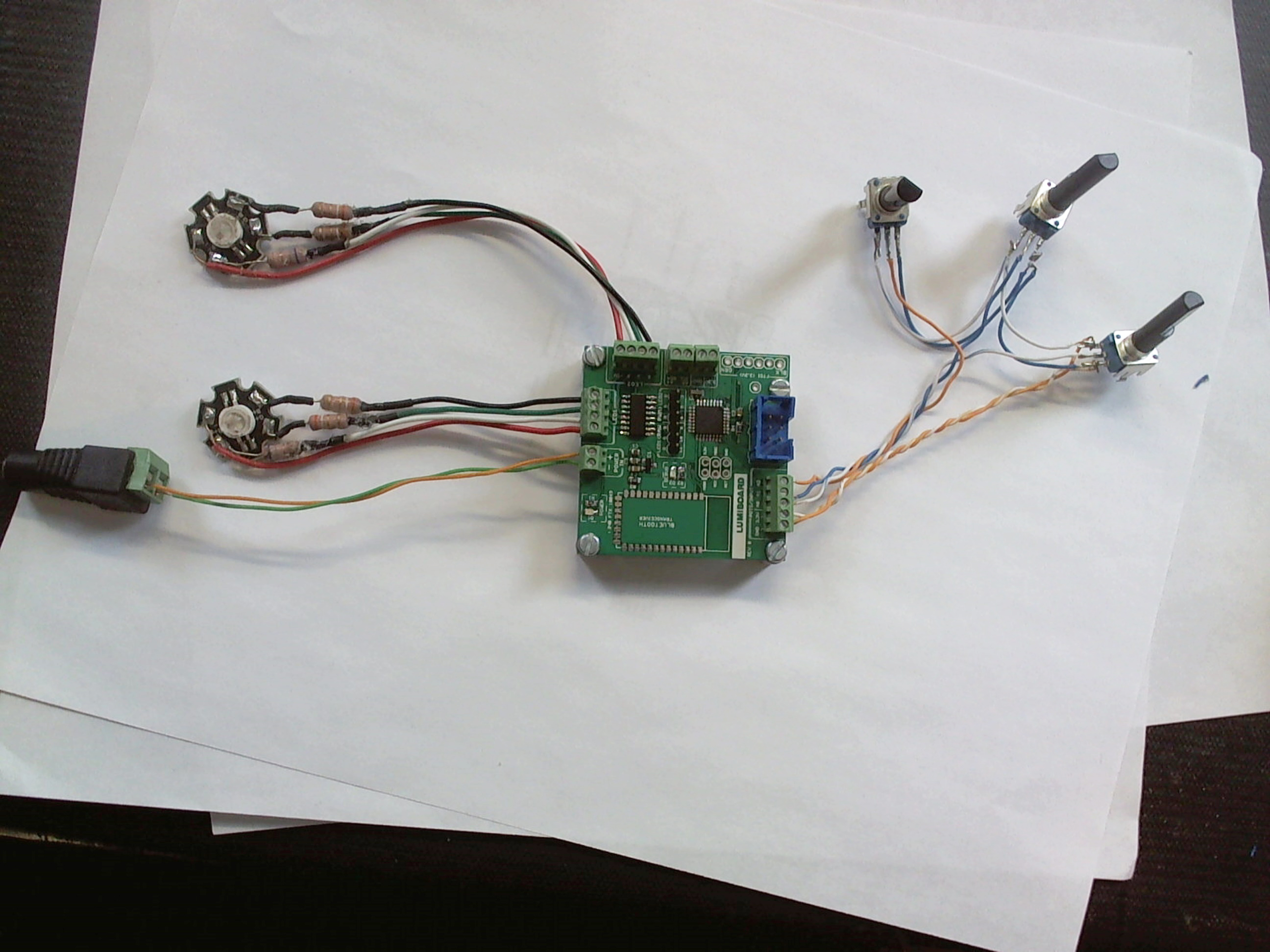 After assembling the board itself, I set out to test each of it’s functions. The most important of which (to me) being the on-board ULN2003 for sinking high-power RGB LEDs. I wired up two 3W RGB LEDs, using simple 2W resistors to limit each channel. Yes, I know I *should* be using constant current drivers, but I’m cheap and the LEDs are insanely bright anyway.
With the series resistors in place, the LED can be directly patched into the screw terminals on the Lumiboard. My firmware allows for one or both of the LEDs to be driven directly with animation patterns or manually using three potentiometers. Here is a demo of what I have working so far:
Early testing of Adafruit NeoPixels (WS2812)
Aside from the high-power RGB LEDs, being able to easily connect to and control NeoPixels (WS2812s) was a big priority for me. These are essentially RGB LEDs that have constant current drivers and control circuitry so that all you have to do to use them is connect +5V, GND and a single digital output pin, and you can control large numbers of RGB LEDs easily.
Adafruit’s NeoPixel Uberguide strongly recommends running NeoPixels at 5V, and shows that a 3.7V battery can do a good job as well. However, it seems to say that 3.3V power and logic (as the Lumiboard would provide) is a bad idea. The Uberguide suggests using a level shifter or lowering the supply voltage of the LEDs to match the level of the logic. Therefore, I felt I would either need to build a level shifter into the Lumiboard or ship a one with every board – both options that didn’t seem good to me.
I decided to connect some NeoPixels to both 3.3V and 5V systems to check out how different they look, and you can find the results in the two videos in this section. At the top right is just a single NeoPixel, while the video below shows a NeoPixel strip and a NeoMatrix running with and without diffusion, and up close.
Conclusion: While the brightness may in fact be quantitatively lower when powering the NeoPixels at 3.3V, the different in brightness is almost imperceptible. 3.3V ain’t so bad!
Testing out Bluetooth with the HC-05 module
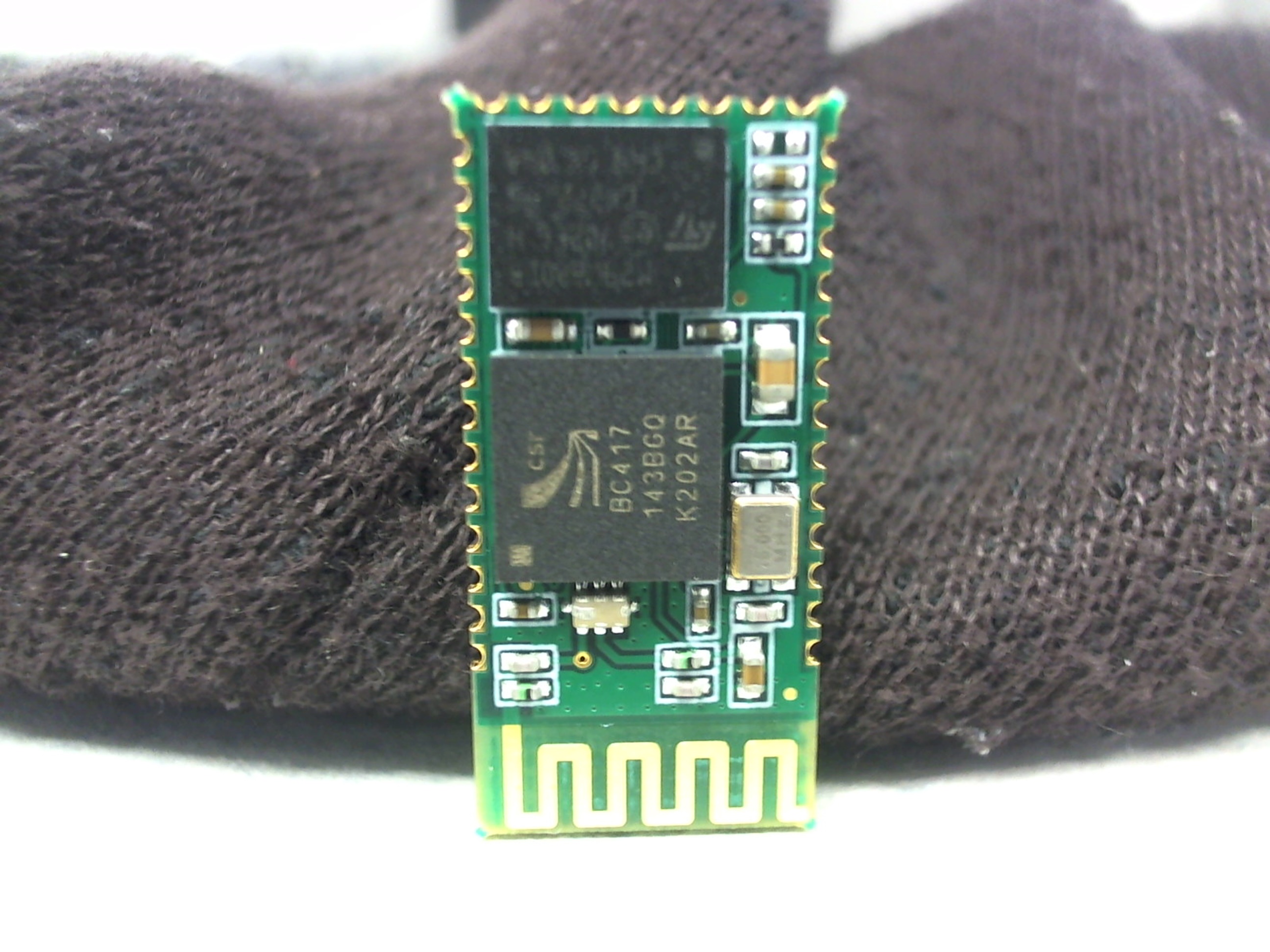 Another big goal for me is to be able to easily communicate with the Lumiboard over Bluetooth so that lighting projects can be controlled remotely via a smartphone or tablet. I’ve included a footprint for an HC-05 Bluetooth transceiver in the board design, and have successfully been able to communicate to the board with it.
I’ve just recently discovered the HM-10 transceiver, which is a drop-in replacement for the HC-05/06 that uses BLE4. A big downside to the HC-05 is that it is not compatible with iOS devices. Honestly this is not a problem for me personally, as I don’t own or plan to own any iOS devices, but if I know that if I can slap “iOS” onto the product description it will suddenly be much cooler. I may not like it, but that’s the way it seems to work!
Just for testing, I soldered up an HC-05 module to my Lumiboard prototype and connected to it via an Android tablet. A simple serial passthrough sketch on the Lumiboard relays messages from the Bluetooth transceiver to a PC via a serial connection (over FTDI). I was able to successfully send and receive messages from the Lumiboard to and from the Android tablet over Bluetooth, as you can see in the following video:
Next steps
I have lots of plans for Lumiboard, which I expect to complete within the next couple months. Some of the things I am planning to do include:
- Test out new 3.3V regulator capable of delivering a whopping 3A of current, so that entire strips and panels of NeoPixels (WS2812 LEDs) can be powered and controlling by the board.
- Make a Fritzing part for the board so that I can easily document how to connect things to the board.
- Test out the HM-10 Bluetooth transciever – a drop-in replacement for the HC-06 transceiver that would allow for connection to iOS devices using BLE4.
- Test out NeoPixels (WS2812 LEDs) – I’ve tested individual NeoPixels, but I need to upgrade the 3.3V regulator to test out strips and panels.
- Make an Arduino library so that users can easily take advantage of all the board features without having to dig through documentation to find pin numbers and specifications.
More information
More information about Lumiboard can be found at the following places:
- Flickr collection about Lumiboard: http://www.flickr.com/photos/zenwebb/collections/72157640611351813/
- Personal project wiki: https://jwwpheadless.com/wiki/index.php?title=Lumiboard
- Github repo: https://github.com/jasonwebb/Lumiboard