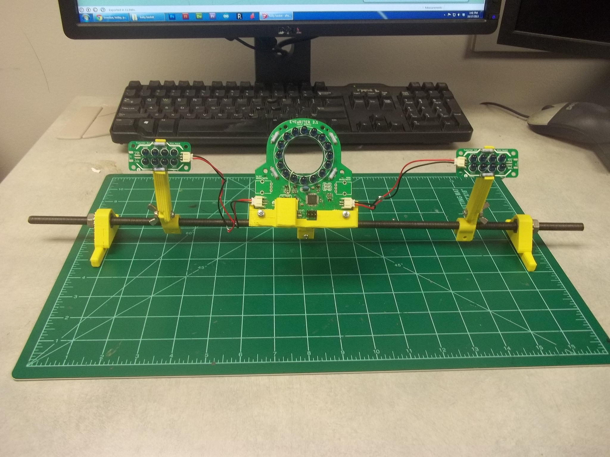
Hardware platform (rev B) for Eyewriter 2.1 eye-tracking system
From the beginning of the Eyewriter 2.1 project I knew that a simple, minimalistic and easy-to-use 3D-printable hardware platform would be necessary to allow users to attach and adjust the electronics and optics system for different usage scenarios such as mounting onto a screen, sitting on a table or working with a laptop.
I took a stab at creating such a platform over the summer and was able to create something that was functional, but needed some obvious revision. Specifically I felt that the original platform used too much plastic and that the ball-and-socket linkage system would not be strong enough to support the hardware that needed to be attached.
Design notes
It was obvious from looking at the original platform that the next iteration would need to use much, much less plastic, so I made sure that was the primary goal this time. In order to do this I had to look at the first iteration and figure out what was necessary and what wasn’t (what parts were doing the important bits).
Moving from two threaded rods to one
I realized that a major contributing factor to the amount of plastic for the first iteration was the use of two parallel threaded rods. Was this really necessary? Originally I thought it was, because I couldn’t think of a way to prevent the parts from spinning around the rod without a second rod in place to stabilize them. I decided to try to use one threaded rod and to try using lock washers to firmly hold the rod in place and prevent it from spinning. But no matter how hard I tightened the nuts, the electronics system would still eventually loosen them and cause the whole thing to fall over.
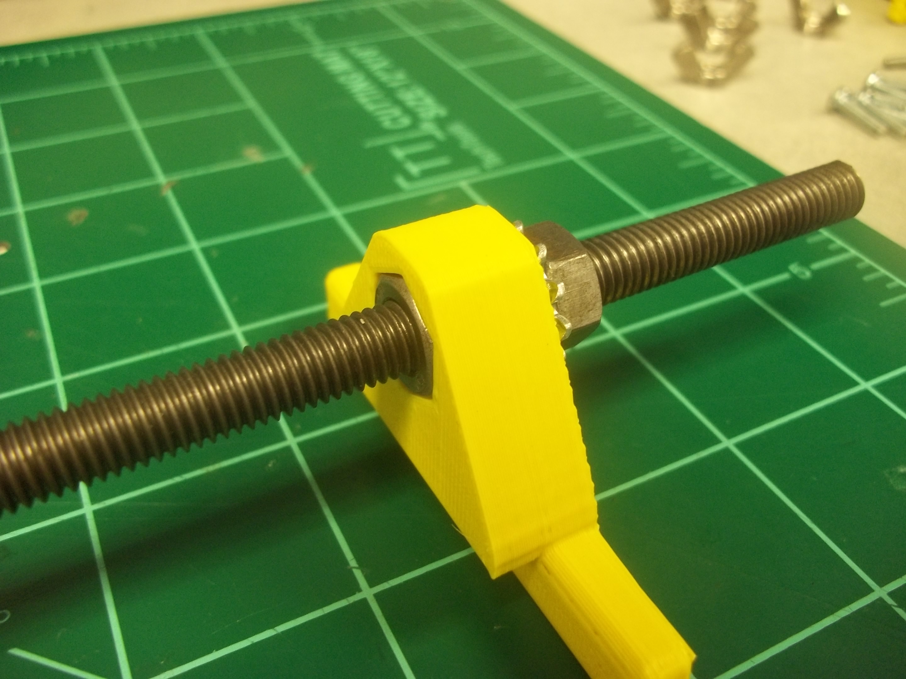
Using captive nuts to prevent twisting
After a while I realized that when the electronics system is mounted to the threaded rod, they act as extended levers that can easily loosen the nuts at the end of the rod. Once I understood this I could see that holding one or more of the end blocks nuts in place would stop this from happening, so I added a captive M8 nut hole to each of the end blocks to test the idea.
List of updates
This new hardware platform includes a lot of updates that should make it cheaper to make, easier to use and more adaptable.
- Uses much less plastic
- Does away with finicky ball-and-socket linkages and instead uses rigid, but adjustable arms.
- Glint modules are statically held at an angle to point at the user’s eye.
- Uses only one M8 threaded rod instead of two.
- Uses fewer M8 nuts (four instead of twenty).
Parts list

There are two types of parts needed to build this platform: 3D-printed and hardware.

All of the 3D printed parts can downloaded from this Thingiverse page.
3D-printed parts
– 2 x end blocks
– 3 x rod clips
– 3 x rigid arms
– 2 x glint mounts
– 1 x main board mount
I recommend printing each of these parts with 40% infill and 0 shells. On the end blocks you can adding 2-3 shells and decrease the infill, but it’s not totally necessary.
Hardware
– M8x~20″ threaded rod (McMaster: 99055A125, cut to size)
– 4 x M8 nuts (McMaster: 90592A022)
– 2 x M8 lock washers (McMaster: 97985A590)
– 8 x M3x14 machine screws (McMaster: 91420A517)
– 6 x M3 lock washers (McMaster: 91120A120)
– 6 x M3 wing nuts (Grainger: 26L006)
– 2 x M3 nuts (McMaster: 90592A009)
– 1-3 x M3x20+ bolt (McMaster: 92005A128)
Assembly
Assembly is pretty straightforward, and greatly simplified thanks to the use of only one threaded rod. You’re basically going to make a 3D-printed kebab!
I’ve made assembly guides in a few different formats, feel free to use whichever makes the most sense to you. There is an Instructable, a video guide and a set of photos on Flickr.

And for those who prefer photos:
[flickr-gallery mode=”photoset” photoset=”72157636781314393″]