openSip+Puff board files sent off for fabrication! Schematics, BOMs, new name, Github commits and more!
After getting a proof-of-concept prototype working two weeks ago, I created a circuit board (PCB) design that integrates the sensor interface from the prototype with all of the necessary circuitry to turn the sensor’s data into useful information and actions like keyboard and mouse presses. Over the weekend I sent this circuit board design off to be fabricated, and am now ready to move forward!
New name (openSip+Puff) and Github commits
Since the beginning of this project I knew I wanted to find a simple, unique and descriptive name that would help people find it more easily online. When you google “sip and puff” you get a great deal of very generalized information, so this project really needed a unique name that would turn up specific and helpful results when someone wants to find it. After a few weeks, I think I’ve come up with a good enough name: openSip+Puff! Hopefully as this project grows and I publish more documentation you’ll be able to find it more and more easily.
Next, I created a repository on Github and pushed all of the most recent source files and documentation for the project. As I hit stable milestones I will publish updates and more files to the repo, so feel free to follow it to see what is going on! Right now you can find datasheets, bills of materials and the Eagle files for the PCB. More will be added over the coming months!

You can also get very up-to-date information from my personal wiki at: https://jwwpheadless.com/wiki/index.php?title=OpenSip%2BPuff
Technical details of the board
In my previous post I described how the sensor interface works (an instrumentation amp and a pressure transducer), but that is just one part of the design. The sensor doesn’t do anything but output data, so a microcontroller is needed to translate and interpret this data and do useful things with it.
I chose to go with the ATMega32u4 to get the job done, due to it’s on-board USB capability and recent popularity in the OSHW world. Using only a handful of parts, this chip can connect to a USB port and mimic the behavior of a keyboard or mouse, requiring no extra software on the user’s side!
The ATMega32u4 the same chip that many new Arduino-compatible boards are based on, including the Leonardo, Micro and Teensy 2.0. Other cool Arduino variants that use the chip include the MaKey MaKey and Adafruit‘s new Flora platform. Clearly this little chip is the hot new thing, even if it costs about twice as much as the current champ, the ATMega328.
- Based on ATMega32u4 loaded with the Arduino Leonardo bootloader.
- Uses a USB mini-B connector for all data and power.
- Uses the MX12GP pressure transducer connected through an AD8223 instrumentation amplifier to an analog input of the ATMega32u4.
Schematics and board files
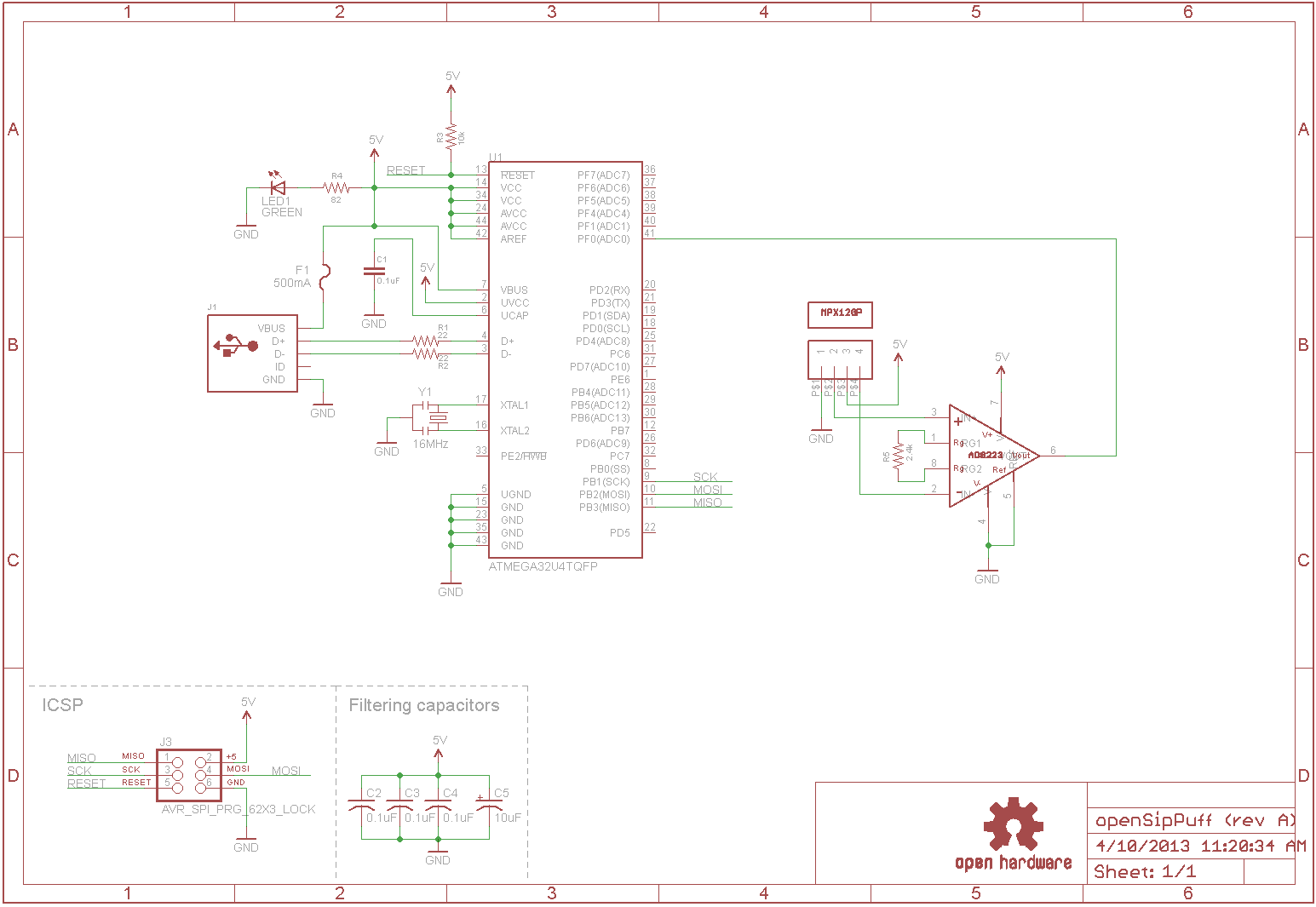
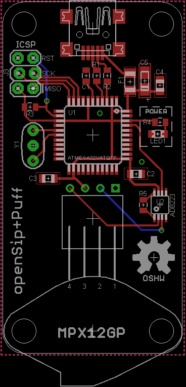
The schematic and board designs came together very quickly, mostly due to their simplicity. The whole design really only has three major parts; the ATMega32u4 microcontroller, the MX12GP transducer and the AD8223 instrumentation amp. Everything else that you see is there to support one or more of these things and make them all work together. In particular, I’ve added four capacitors that I see in all of the other ATMega32u4-based variants, which I assume are good for power filtering and decoupling (probably very important for USB devices).
A note about the sensor mounting
I wanted the MX12GP pressure transducer to sit flat on the PCB, but the four leads coming out from it stick straight out the bottom, meaning that the manufacturer seemed to have designed it to sit vertically on the board. I decided to use a 1×4 right-angle female header to connect the sensor to the board, which has the side benefit of making it very easy to replace the sensor in the future. Since the sensor is not permanently fixed (glued or soldered) to any part of the board, this should help serviceability in the future.
Bill of materials (BOM)
To accompany the above schematic, I’ll include a bill of materials for all of the electronic bits that will be needed to build one board. Pretty much everything is from Digikey, but I want to make a note that the standoffs are not the standard #4-40 variety. The MX12GP includes two M4 mounting holes, so each of the holes in the PCB corners are meant to accommodate M4 screws, which will eventually be screwed into a 3D-printed housing.
Fabricating the boards
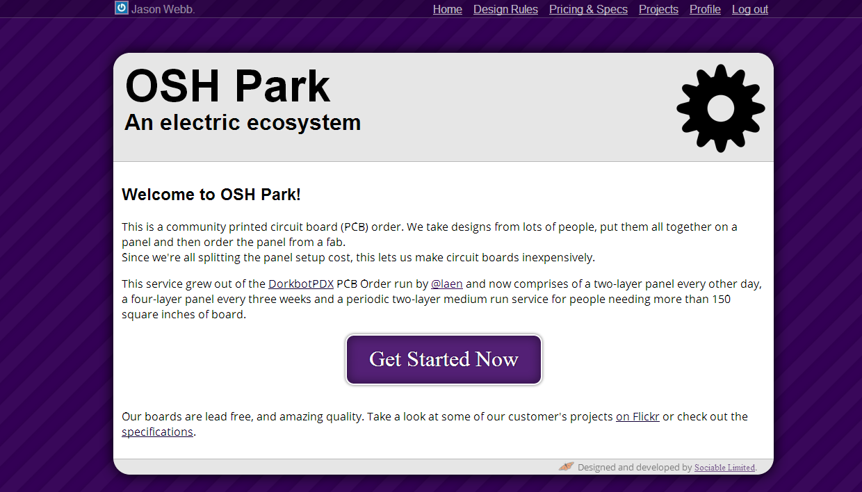 These days it is actually really easy and quite cheap to get boards of this side fabricated for you, thanks to hobby PCB services like OSH Park, Seeed Studio and Smart Prototyping. For small boards like this, I prefer OSH Park because they offer a very high-quality, low-cost, US-based service with free shipping.
These boards only cost $13.70 for three boards through OSH Park, with free shipping!
One new feature that OSH Park has added since the last time I used them is the ability to upload a .brd file made with Eagle straight to the website for processing; no CAM work involved! Unfortunately, this does ignore any fancy silkscreen work you may have on non-standard layers though. I like to use tDocu and bDocu for random text and outlines, but the site ignored those. I changed them to tPlace and bPlace instead and it worked fine.
Next steps
Before the PCBs arrive at my house I will purchase at least one set of components. I am also working on a 3D-printable clamshell housing that the PCB will be mounted into, providing a simple, durable and attractive way to hide all the “ugly” bits from end-users.