Interactive moving lights built for KANEKO’s PLAY exhibition
 About one month before the opening of KANEKO‘s recent PLAY exhibition I was asked to propose and build out a number of playful interactive pieces that the public could interact with for the duration of the three-month show.
One of the projects I proposed was this series of three whimsical control panels that would control the movements and behaviors of three high-power LED floodlights. In the span of about four weeks I designed, fabricated and installed this project for KANEKO (just in time for the opening day). Happily, the project held up quite well and lasted the entire duration of the exhibition with surprisingly little maintenance required!
Table of contents
System concept and design
The concept for this project began in a somewhat freeform way – make three unique control panels with three lights attached to moving armatures. Compared to other projects that I’ve done this concept was executed pretty much on the fly following my intuition rather than spending weeks meticulously designing every aspect of the project up front.
Right away I knew that each control panel would contain the following elements:
- Microcontroller to run everything – I opted for the Teensy LC
- Pan/tilt servo mechanism with a 10W RGB LED floodlight attached
- Interesting input devices such as buttons, switches, piezos and more
- Power supply to power the microcontroller, pan/tilt servos and any input devices
Each of these components would then be connected in the following way:

Parts list
Once the concept and overall system had been designed I began compiling a bill of materials (BOM) containing sources, prices and notes for all of the materials to be used in this project. Most of the materials were obvious from my initial sketching and design work, though some of it (such as the spray paint) were added later on the project as they came up.
As with any project this list is not entirely complete due to last-minute needs and changes, but I’d say this list is about 90% accurate to what I used.
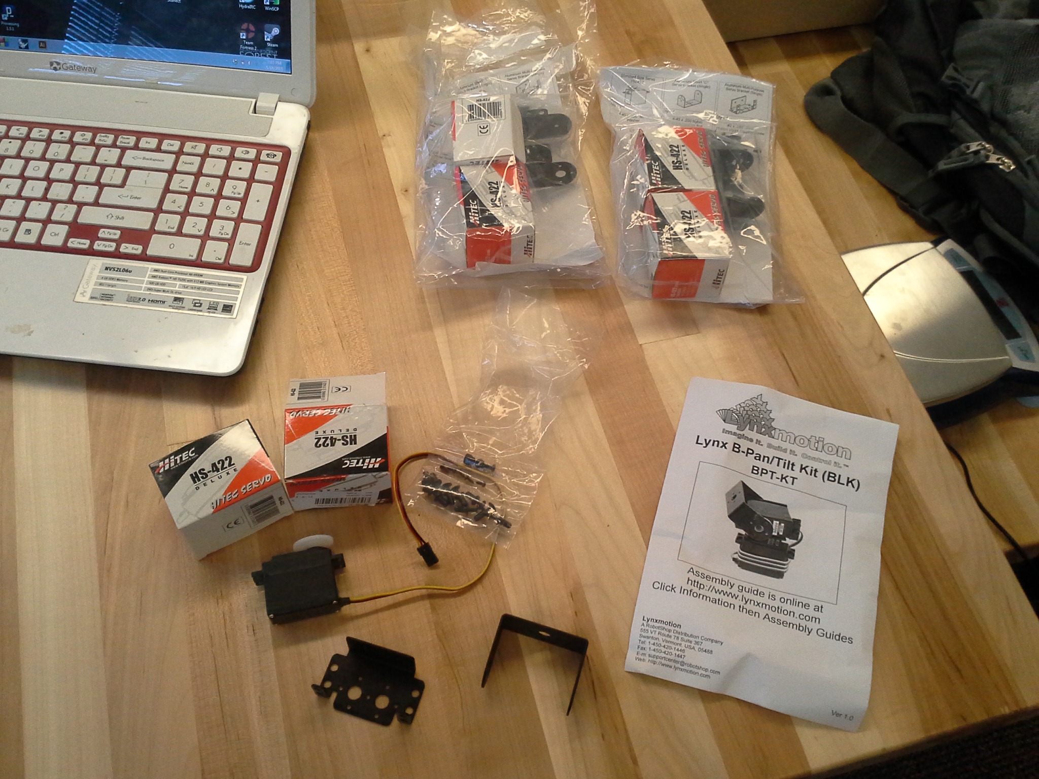
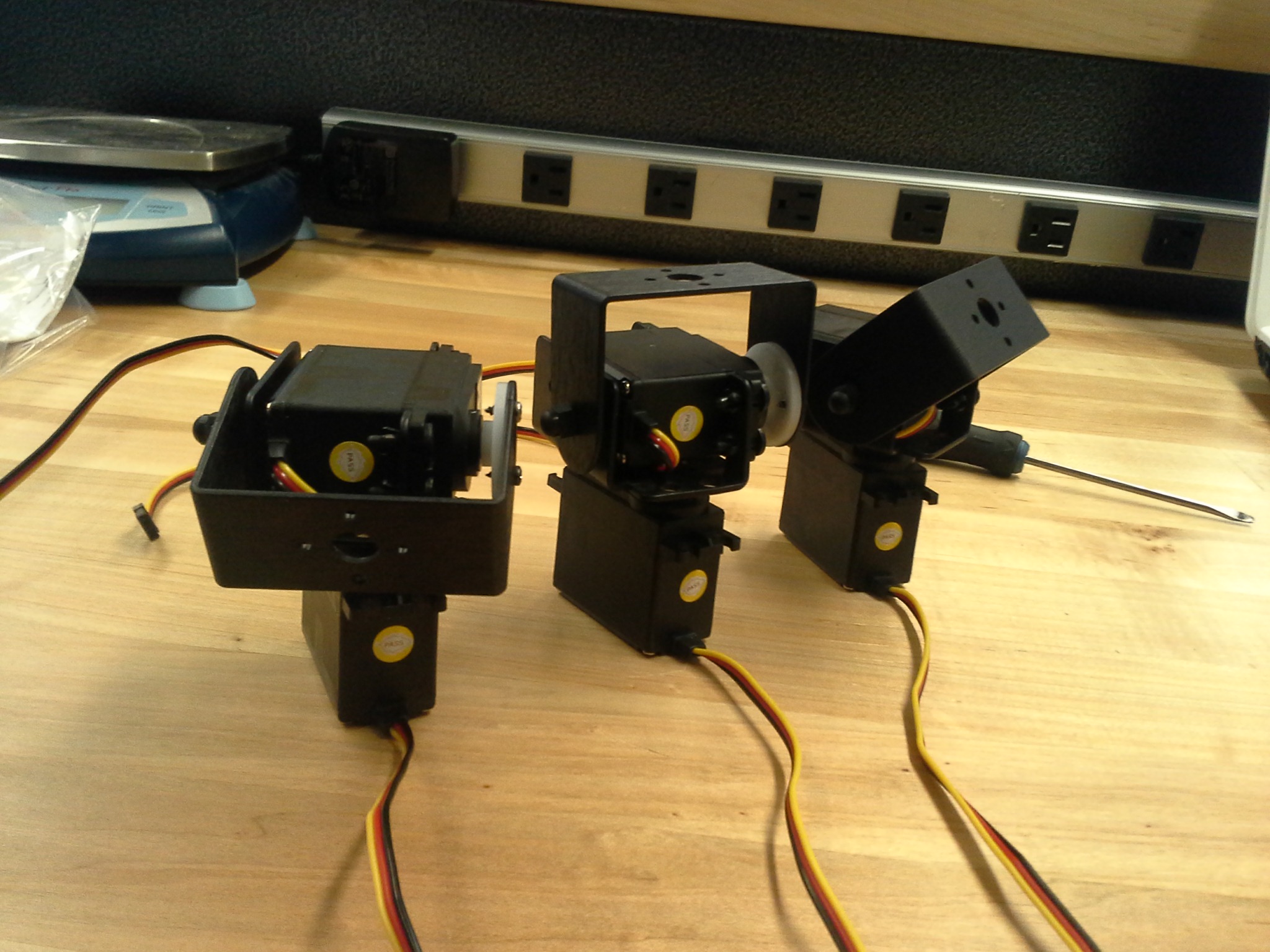
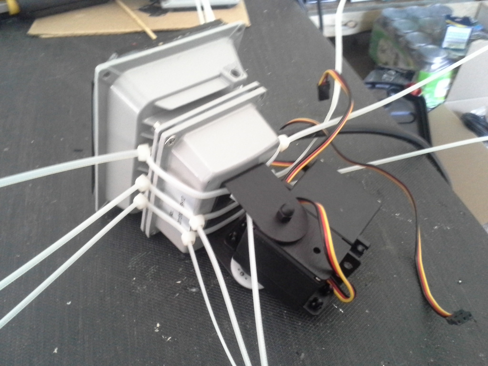
Assembling the pan/tilt mechanisms with lights
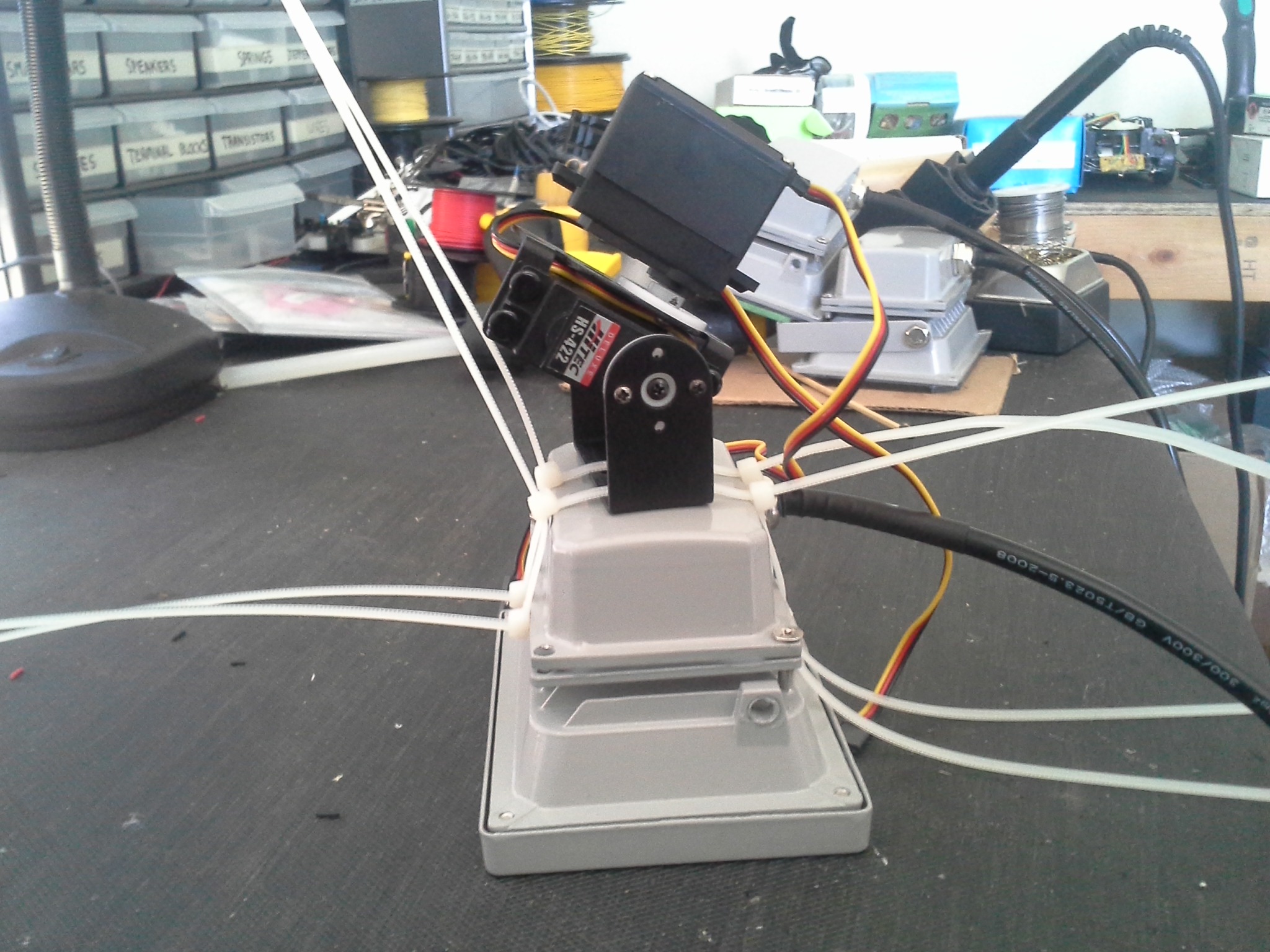
First up I ordered some high-powered 10W RGB LED floodlights from Amazon, along with pan/tilt mechniams (with standard servos included) from Lynxmotion. The pan/tilt mechanisms required a little bit of assembly, but this was super easy thanks to the very clear included instructions.
To attach the LED floodlights to the pan/tilt mechanisms I opted to use some zip-ties rather than epoxy, thinking that it was more likely that the servos or pan/tilt mechanism would need some fixing during the exhibition. However, this decision turned out to bite me in the butt near the end of the exhibition as the servos and hardware all performed great while the zip-tied floodlights became a bit of a target for some overly eager kids who preferred to grab the lights and move them by force rather than use the control panels! While I still feel like epoxy was too much of a risk during fabrication (not knowing how the servos would perform), another solution besides zip-ties would have been smart.
Panel design and fabrication
Next up was the design and fabrication of the control panels themselves. I decided to keep the control panels simple and unique so that they could be made in a reasonable amount of time, which for me meant simple primitive shapes, different colors and no more than a handful of different input devices per panel.
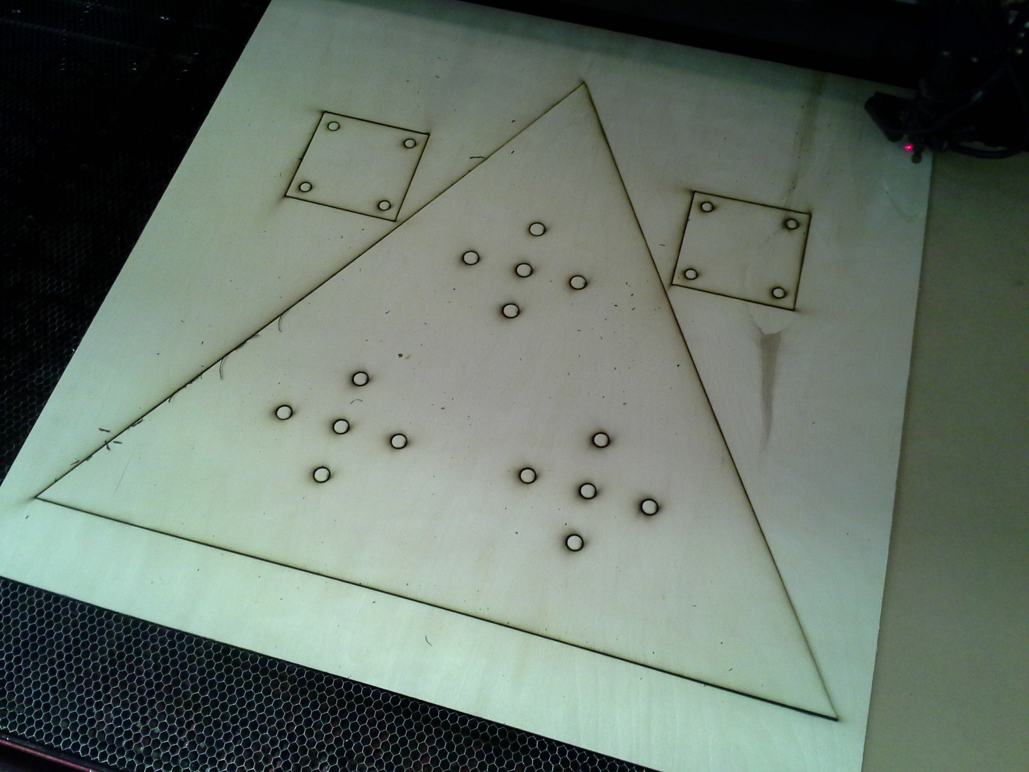
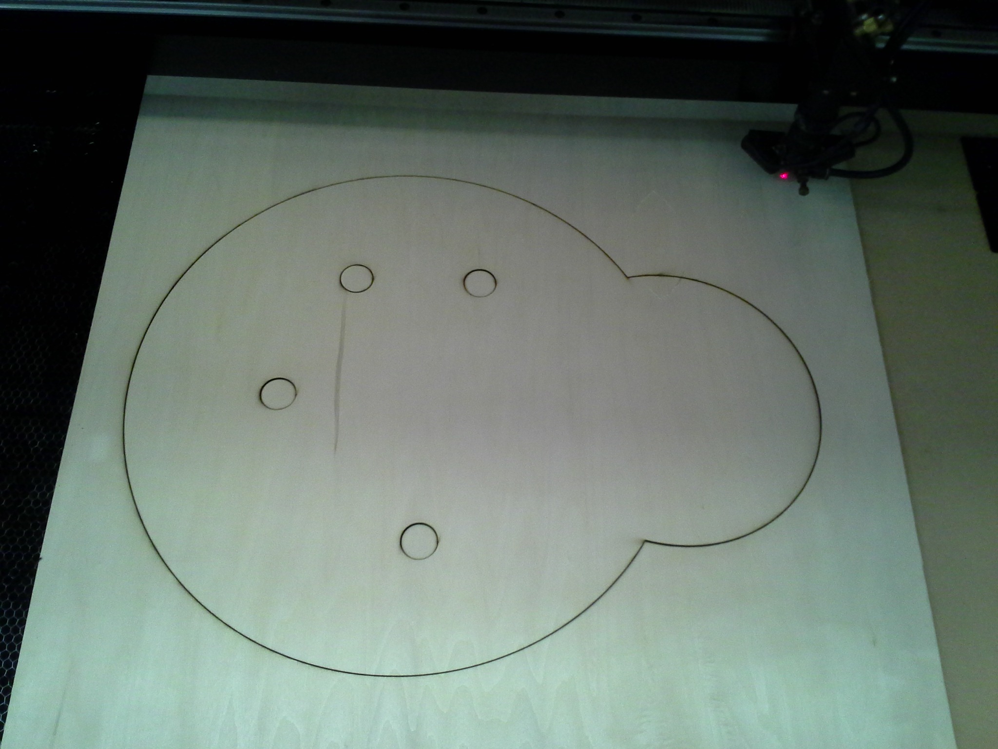
Since nearly all common buttons, switches and other input devices are intended to be installed on materials that are no more than 1/4″ thick, I opted to use two layers of thin plywood for each control panel. The top layer of wood would contain mounting holes for all the input devices, while the bottom layer provides structural support to prevent warping and stand up to abuse, with larger cutouts to allow for wiring and part placement.
I whipped up some vector designs for each layer of each panel, with the exception of the red square panel, all of which are available on the project’s Github repo.

After designing the panels and verifying part placements and mounting hole dimensions I headed over my local FabLab to use their laser cutter. Thankfully this process is fast, simple and results in excellent pieces far nicer than I could produce through any other method, allowing me to spend more time on more creative aspects of the project.
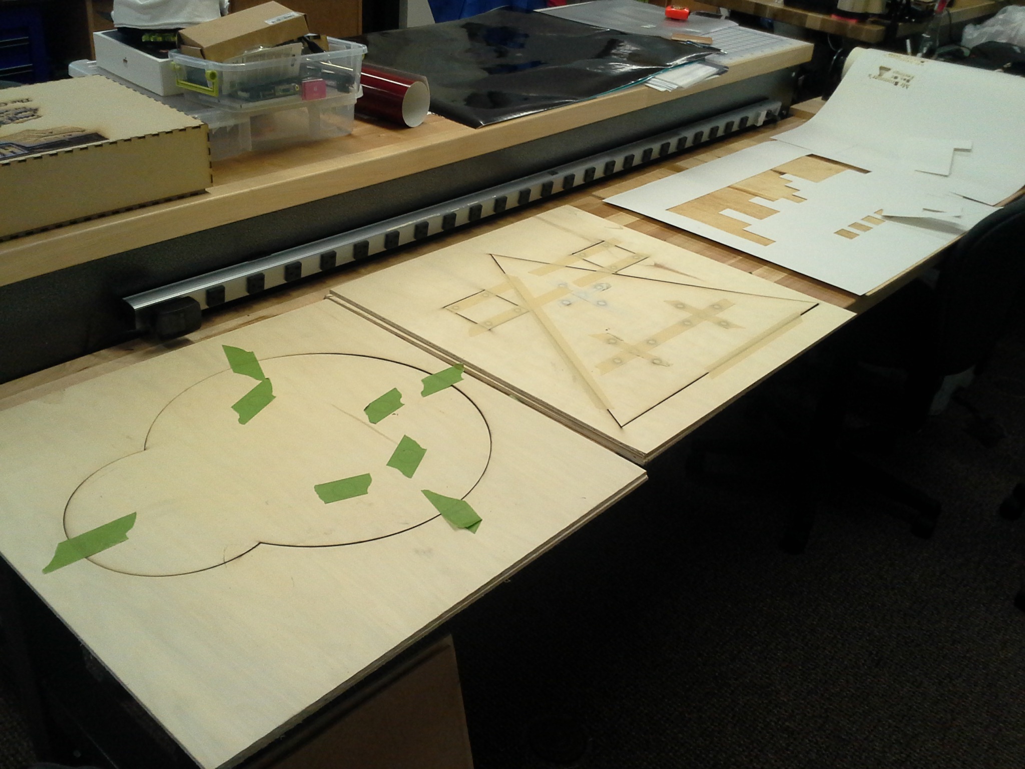
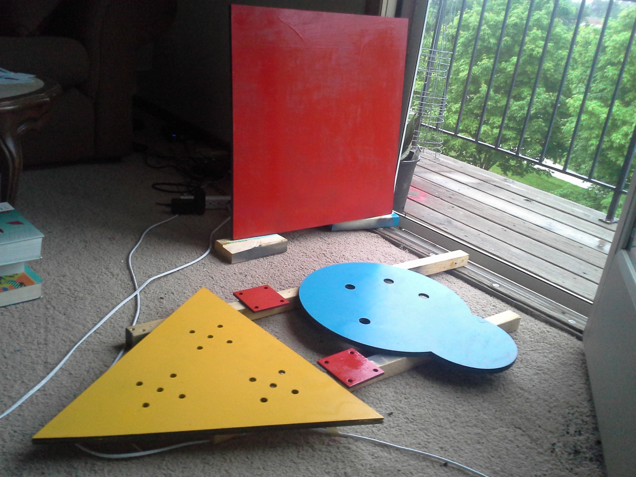
After cutting the pieces they were ready for a coat of primer and some snazzy spray paint. Easier said than done when you don’t have decent studio space! Nonetheless, a tarp on my tiny balcony helped me get the job done!
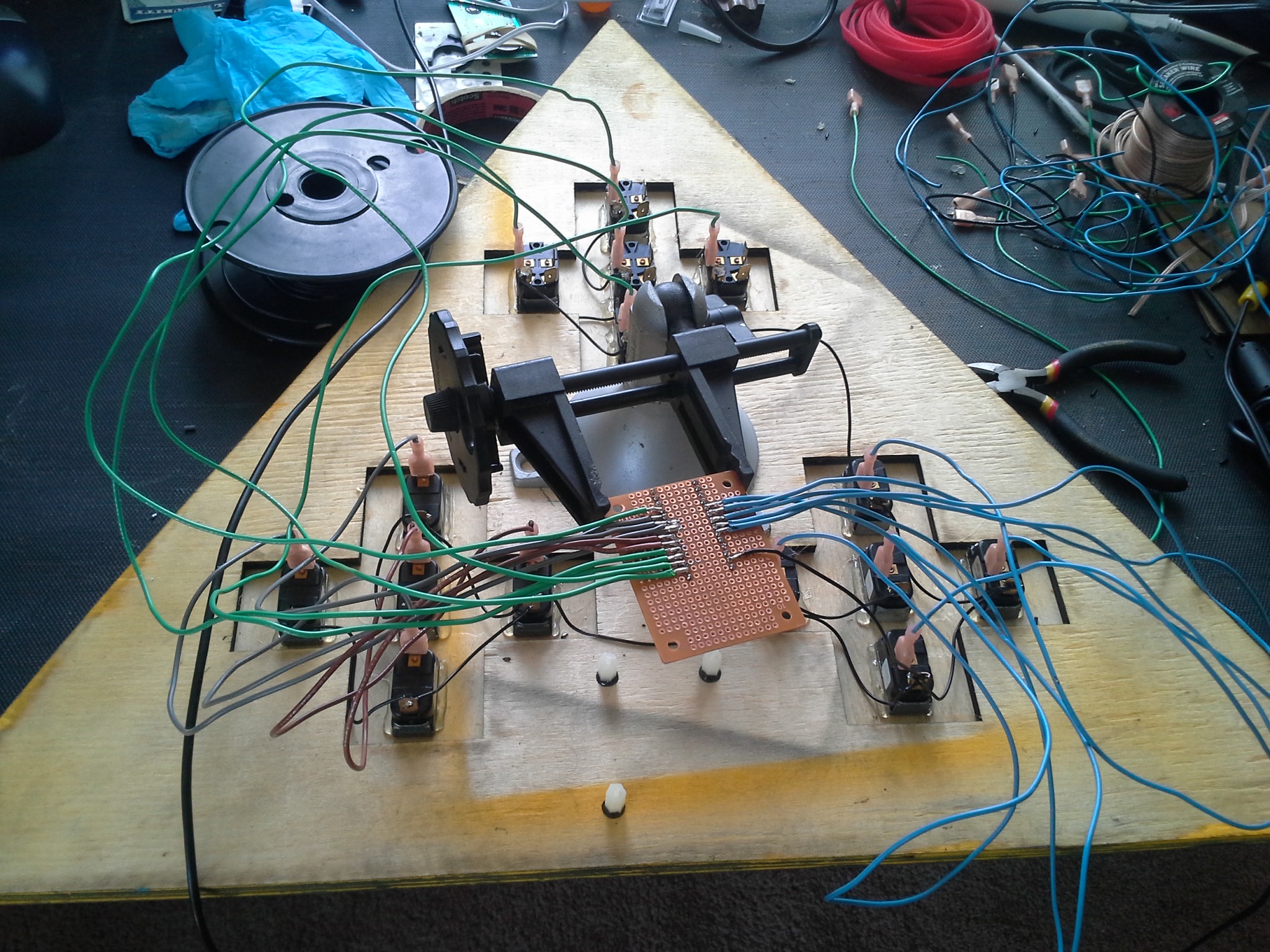
Panel wiring
Once the spray paint had dried and all of the electronics parts had arrived it was time to install all the parts and get them wired up to their respective microcontrollers. Since I wanted each panel to feel very different, I decided to use different types of input devices for each one, all requiring different wiring and code.
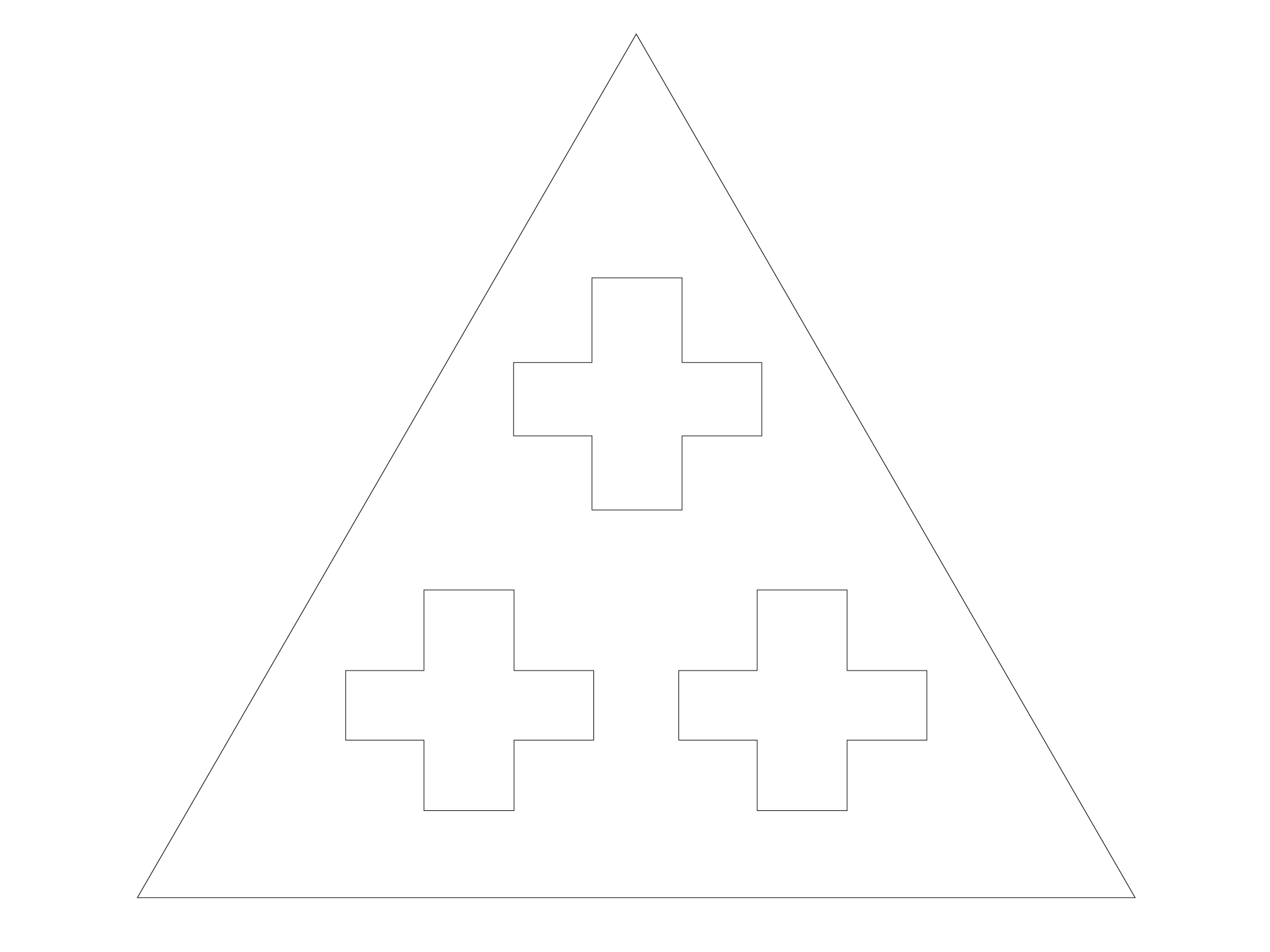
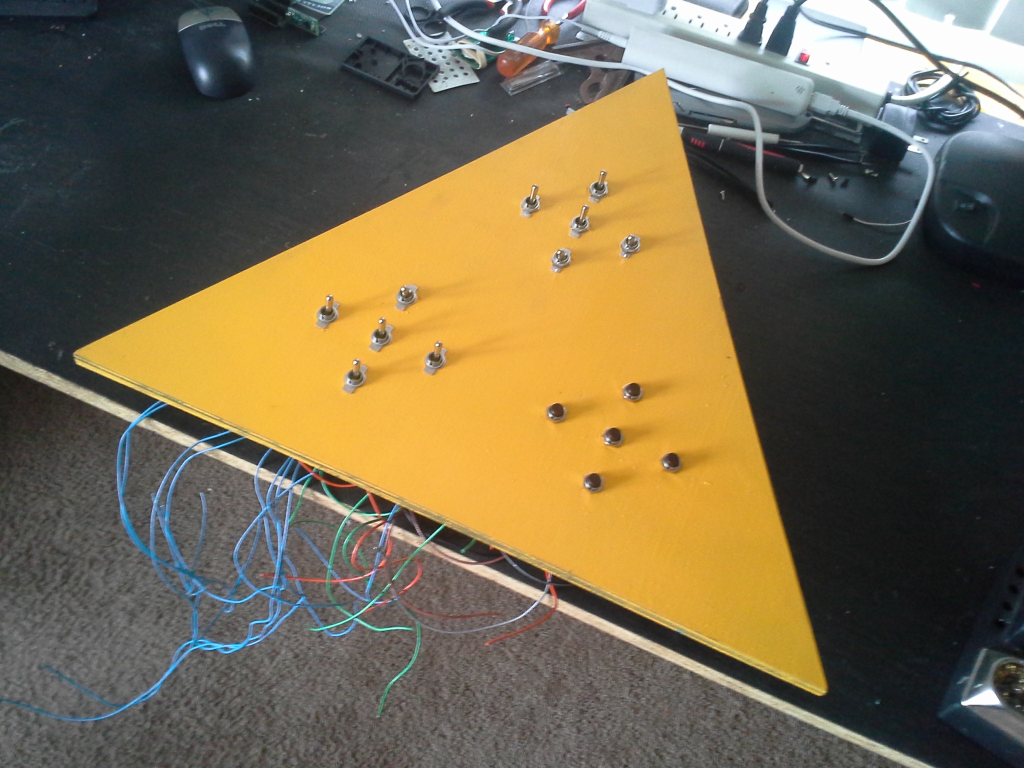
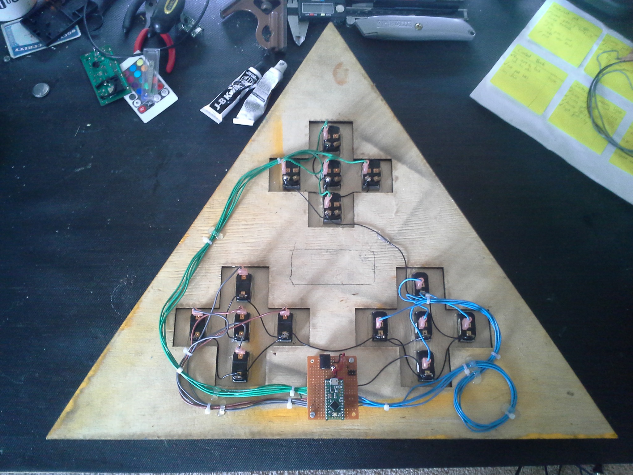
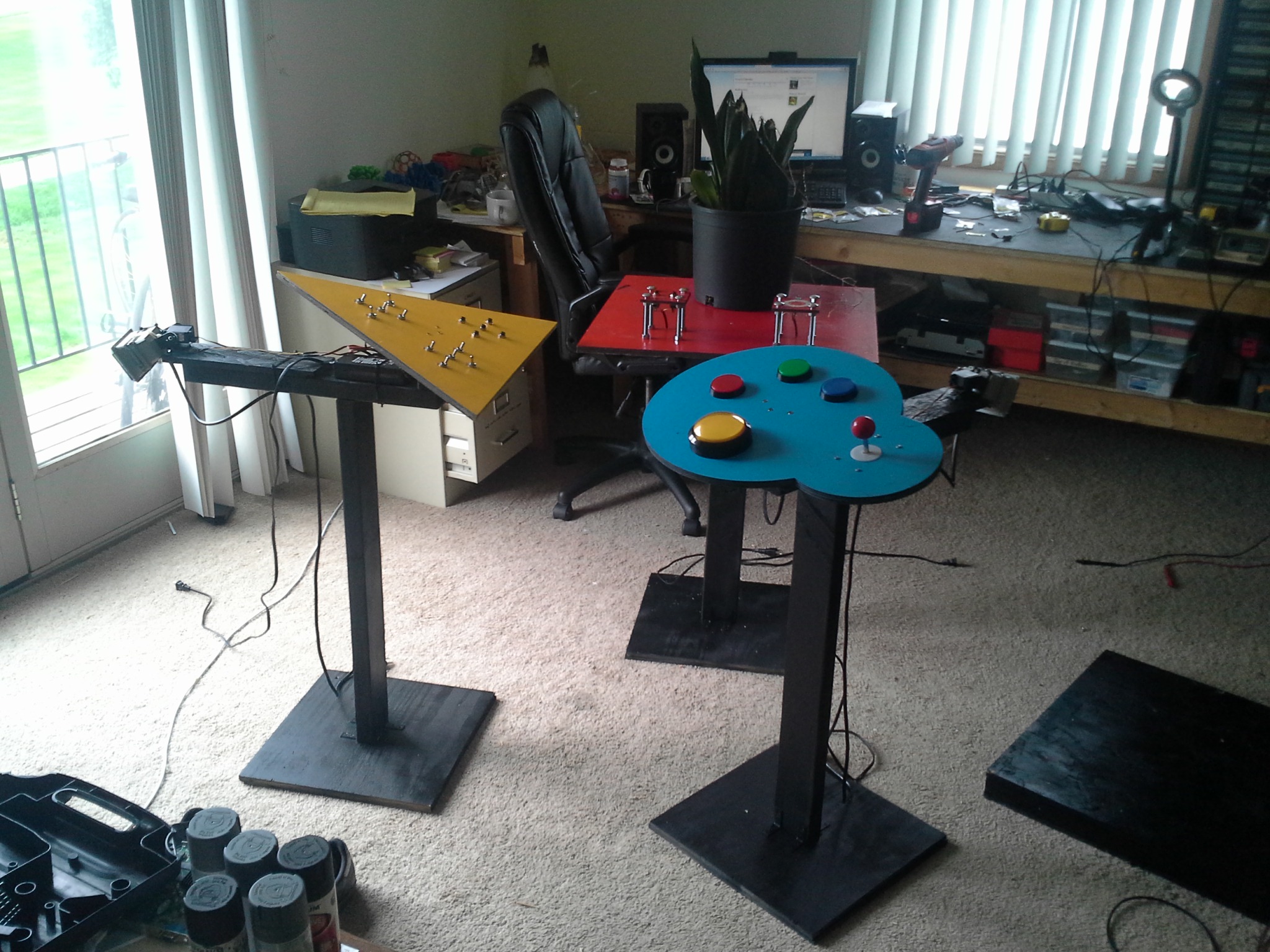
Yellow triangle
This panel made use of some salvaged industrial-looking toggle switches and momentary pushbuttons to create a classic retro spaceship feel. By making use of internal pull-up resistors included inside the on-board Teensy LC’s main chip no extra parts are required and the switches can all be wired up directly to the Teensy LC.
A shared ground connection is daisy-chained to all switches, effectively allowing each switch to toggle their respective Teensy pins from +5V (HIGH), through the internal pull-ups, and ground (LOW).

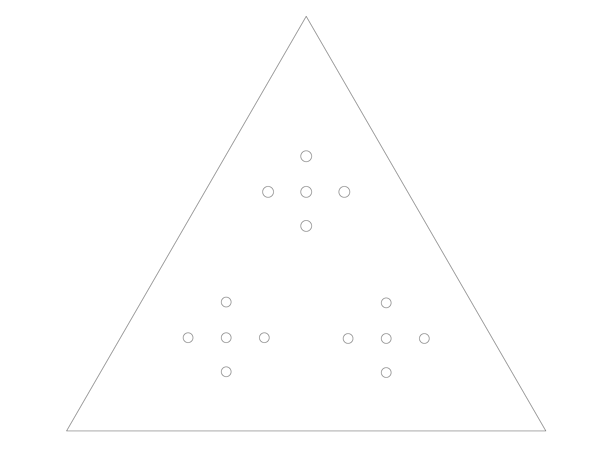
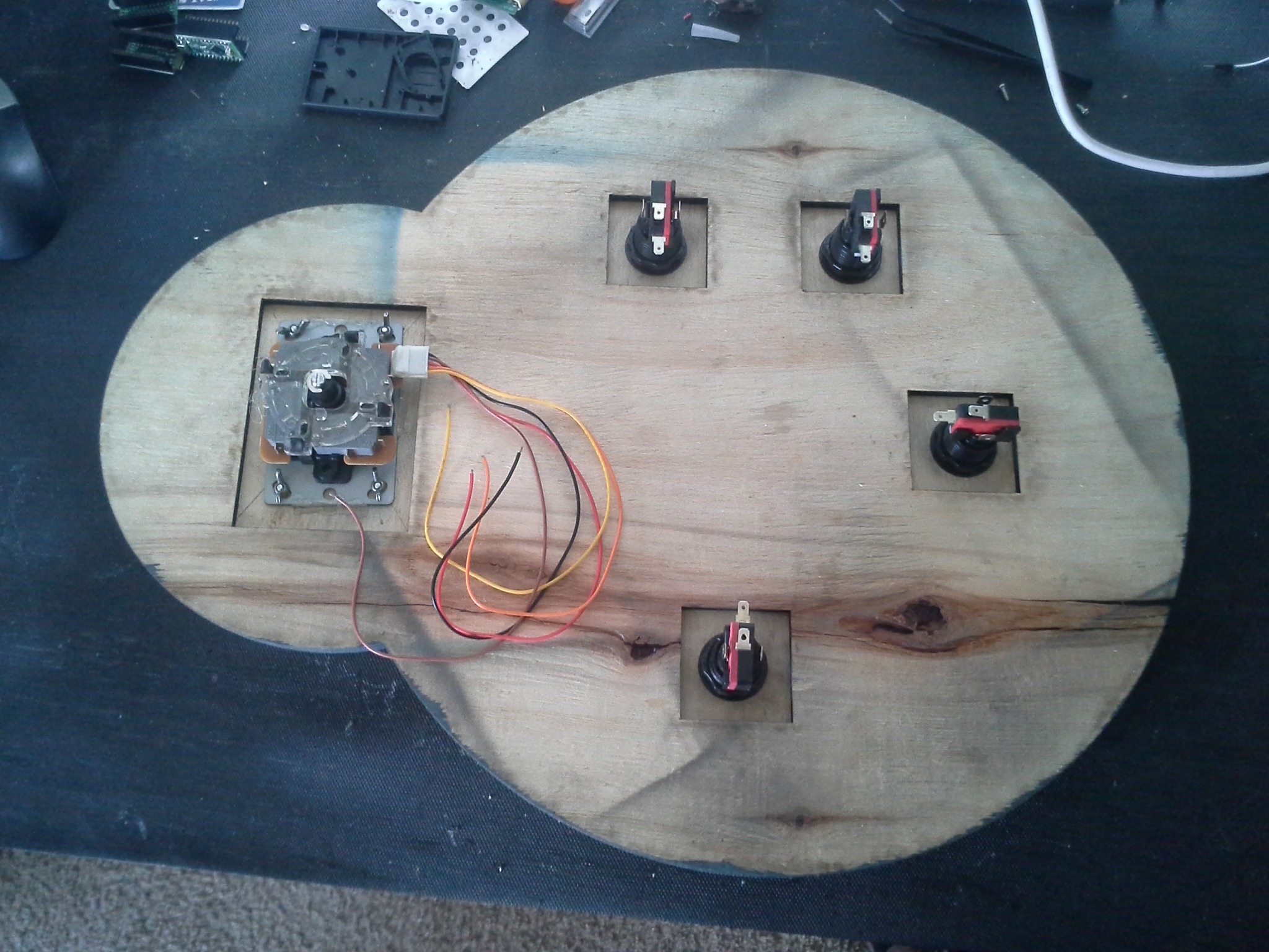
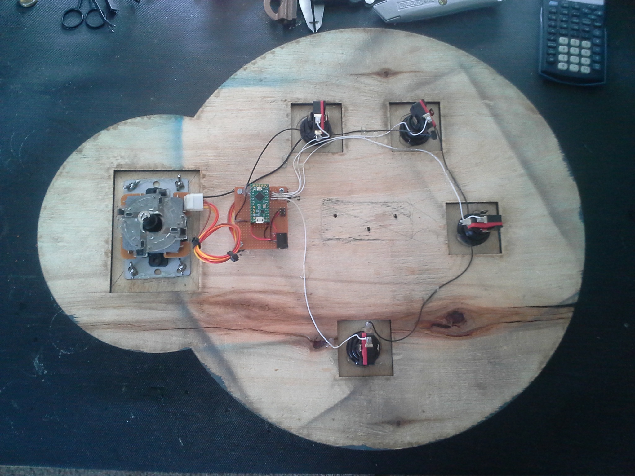
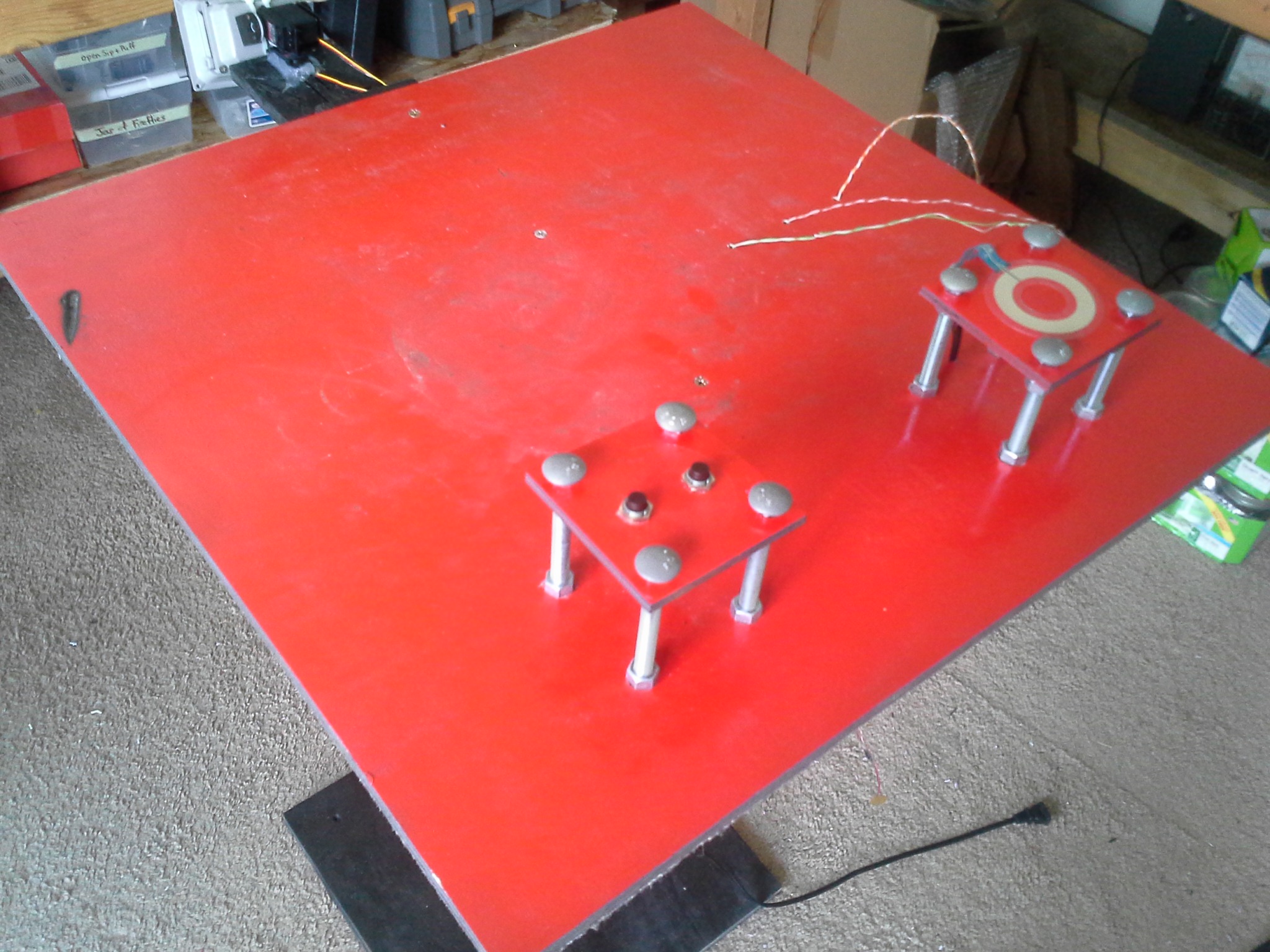
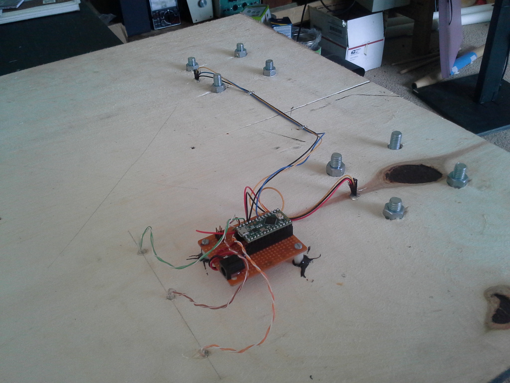
Blue circles
The blue panel made use of four large arcade dome buttons (one 100mm and three 60mm) and an arcade joystick, all purchased from Adafruit. Just like the yellow triangle, all of these components are connected to unique pins of the Teensy LC, along with a shared ground connection. Anytime a button is pressed, their respective Teensy pin goes from HIGH to LOW.

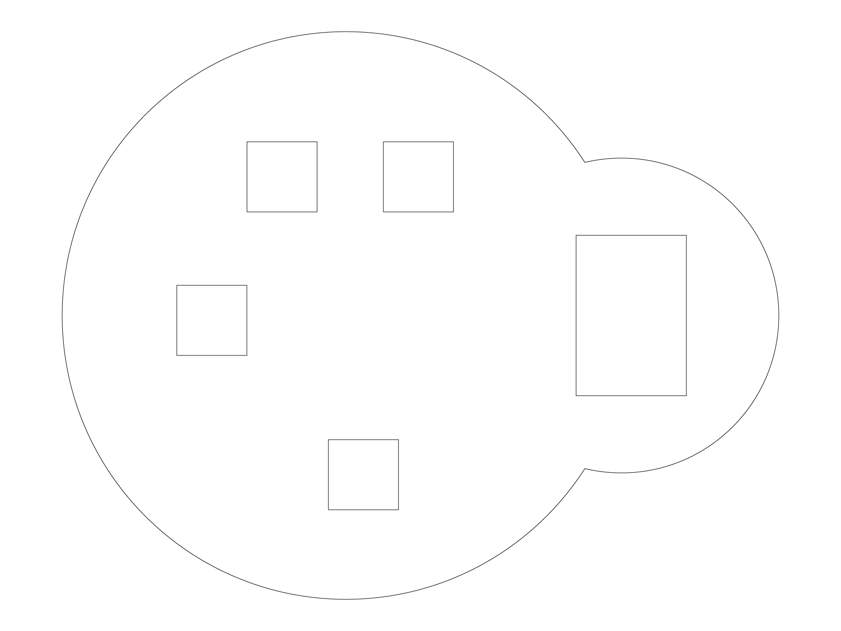
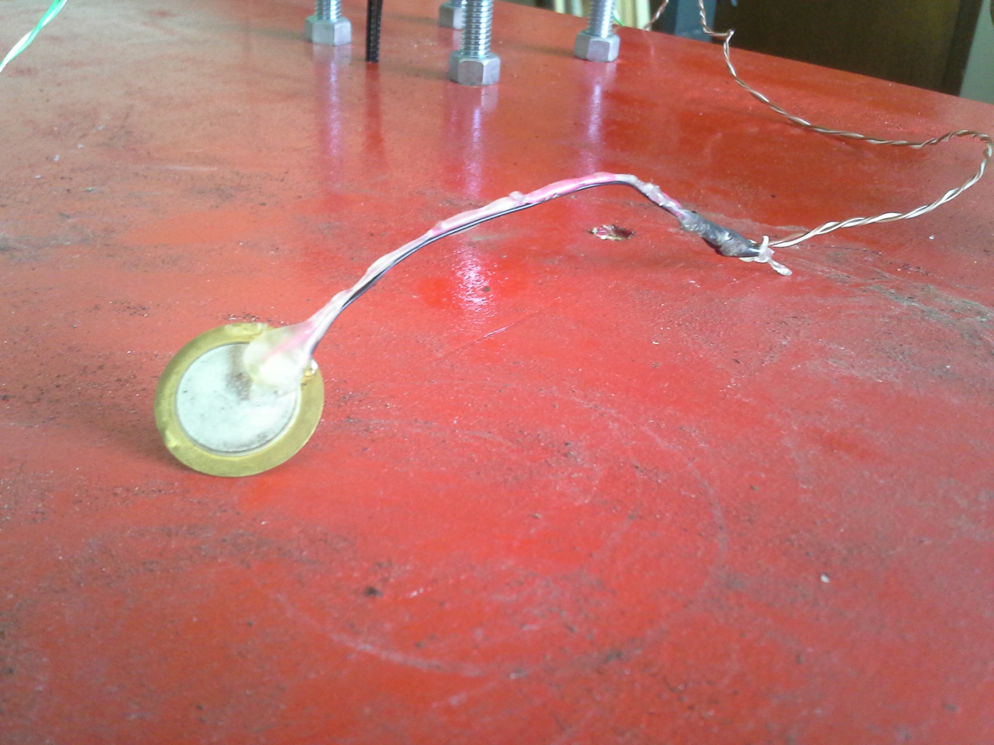
Red square
Compared to the other two panels, this panel was much more wacky and experimental, making use of a circular SoftPot, two momentary buttons and three piezo transducers wired to act as “knock” sensors.
Coding
After each panel had been fabricated, assembled and wired up some firmware needed to be written for the Teensy microcontrollers to make them all function.
Even though each panel has different controls, they all use the same servo-based pan-tilt mechanism for the lights, and therefore share similar code patterns to turn the various inputs into motion. At first I had the various controls result in direct and somewhat obvious control of the up/down and left/right motions of the lights, but that just didn’t feel playful enough during testing.
Instead of resulting in direct control of the lights, most of the inputs trigger pre-programmed “animations” such as moving the light in circles, shaking left/right and so on.
All of the code for each panel is available via the project’s Github repository for anyone who wants to see how it was all done!

Mounting
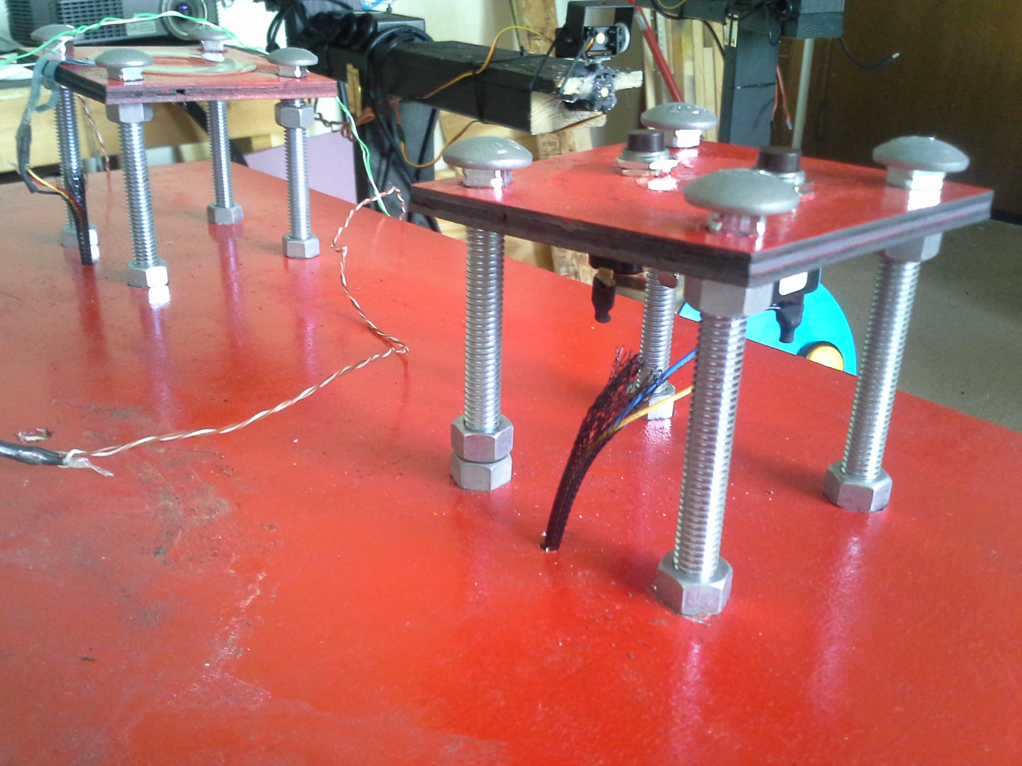
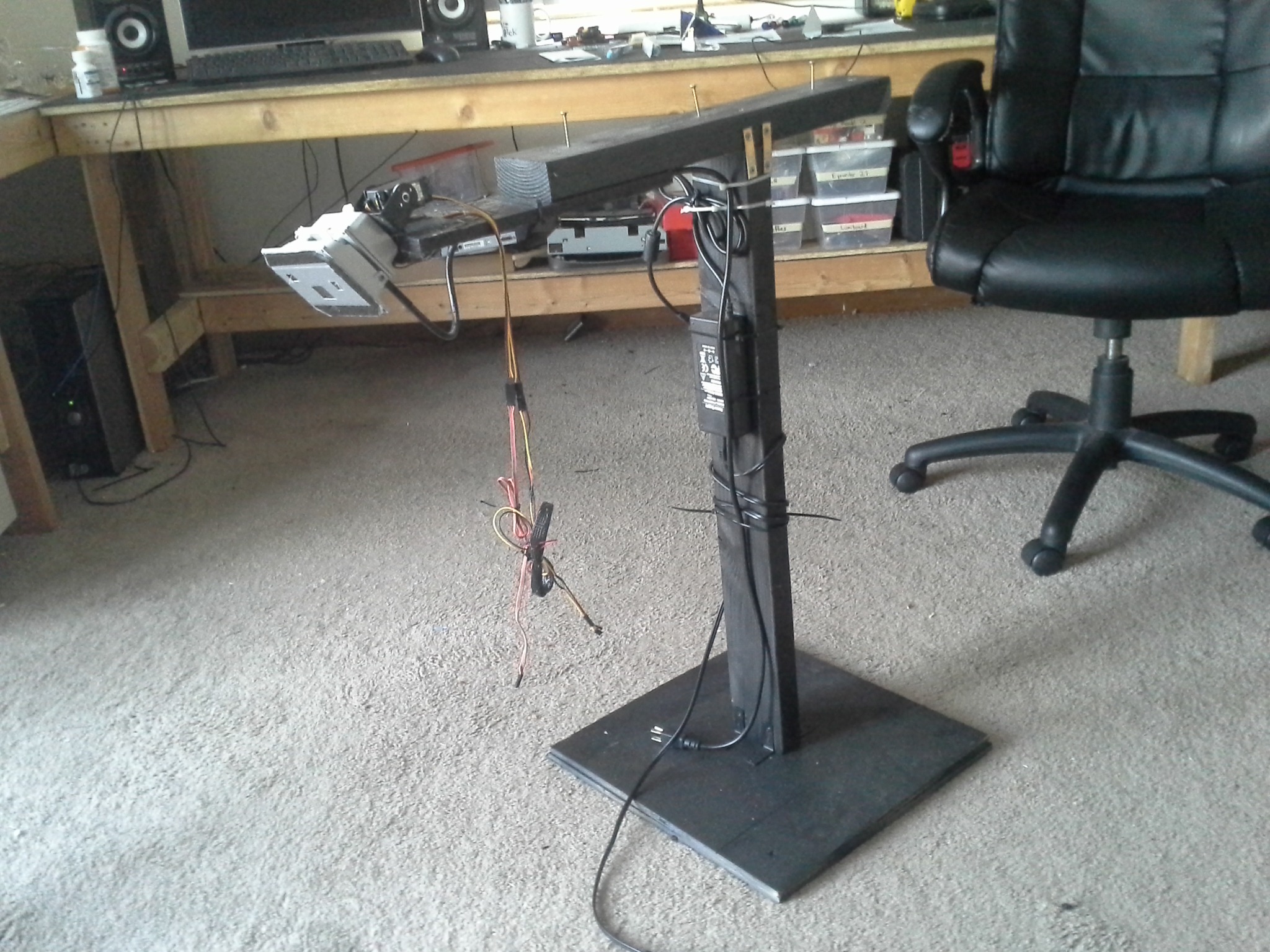
To install these panels at the venue I needed to whip up some simple mounts that would make them easy to transport and reposition, as well as look good. At this point in the build process I only had a few days left and little to no budget, so I used scrap wood (painted black) to construct some minimalist mounts that held both the panels and their respective LED floodlights, while also helping to organize the wiring and bit.
All in all the mounts served their purpose very well, with one pretty big exception. Since I did not know how the serves and lights would perform over time, I didn’t want to over-engineer a complex mounting solution for the pan/tilt mechanisms and instead opted for my go-to approach – hot glue. It worked for a couple weeks, but the heat of the motors eventually dried out the hot glue and caused it to separate from both the wooden mounts and the servos themselves, causing the lights to droop or fall off entirely on some of the systems. Some silicone was used at one point to repair one of the mounts, but before we knew it the exhibition wrapped up and everything needed to come down anyway.
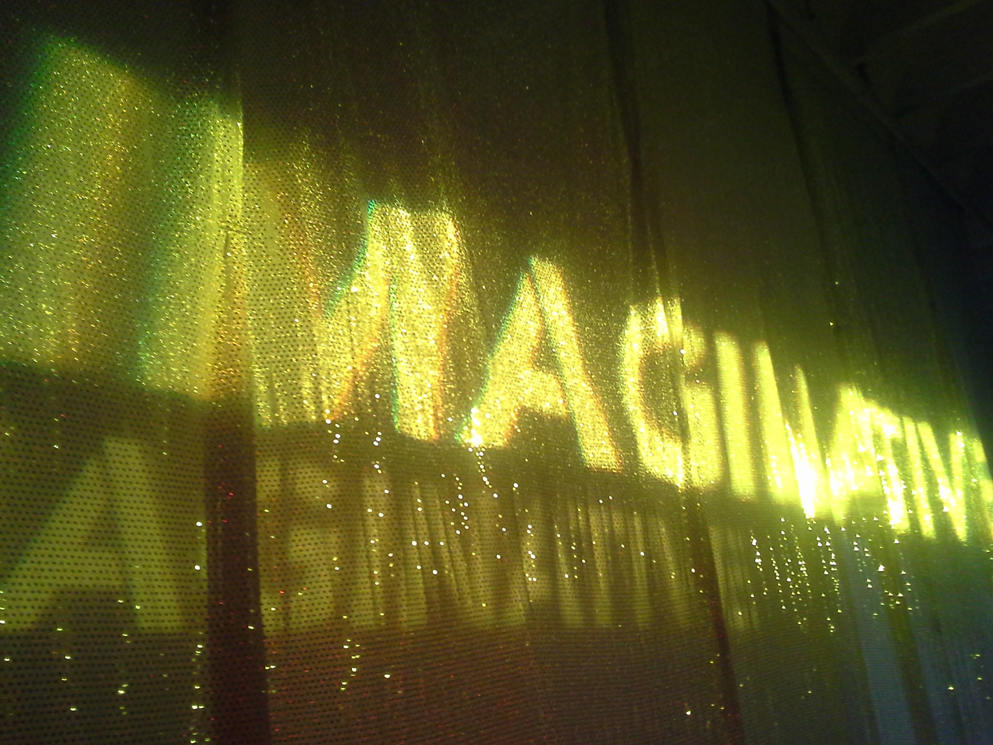
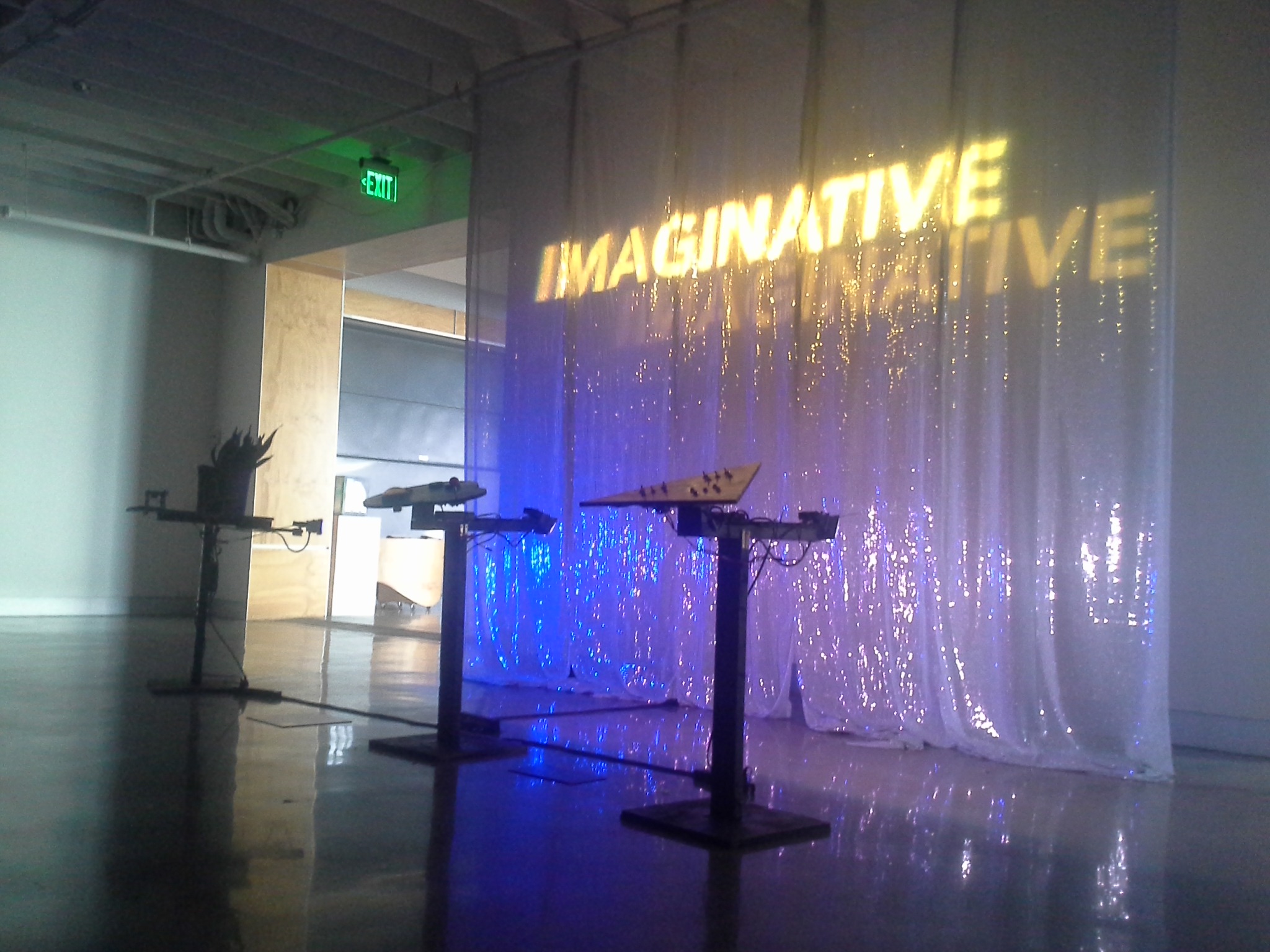
Installation at KANEKO
As soon as everything was put together and working pretty well it was time to drive the pieces out to KANEKO and install them. Since they are freestanding, very little needed to be done – just drag them into place and plug in the power! KANEKO provided a neat semi-reflective curtain to project lights onto, and things more or less came out as I was hoping.
Conclusion
Overall this was an extremely fun project to execute and I’m really happy to have had the opportunity to get involved! Despite the inevitable, and mostly trivial, hiccups along the way, I think that the visitors had a great time interacting with the pieces and (hopefully) seeing technology being used in a new and playful way.
A huge thanks goes out to Michael Hollins and Mike Echternacht at KANEKO for inviting me to get involved in this exhibition, and to all of the KANEKO team members who helped to install, maintain and deinstall the pieces at the venue!