Prusa Mendel build update #3: frame tightened, X, Y and Z axes assembled
After getting a little bit burned out last week from working on my aquaponics system, I spent the weekend making quite a bit of progress on my Prusa Mendel (i2) 3D printer. I’ve known what the next steps in building the machine where for a while, but just hadn’t gotten around to doing it!
I’m following the official build manual from the RepRap wiki and trying to stay as close to them as I can. This post is basically a collection of my notes from steps 2.5 (Tightening the Frame) through 2.9 (Installing the X Carriage).
Y axis
The Y axis consists of a flat piece of material (I’m using 1/8″ birch plywood) called the “print bottom plate” that is attached to four LM8UU linear bearings using some 3D printed bearing holders. The build manual only talks about a type of bearing holder that must be glued to the print bed, which I really didn’t want do. It doesn’t say anything about the bearing holders that are actually included in the master Github repo for the Prusa Mendel i2, which include a flange with two M3 bolt holes. No glue needed!
Mounting the bearings
The bearings slide along two pieces of smooth rod (two bearings per rod) that are almost perfectly parallel. Getting the smooth rods to be parallel was surprisingly easy thanks to the method outlined in the build manual of using the print bottom plate to ensure the spacing of the bars.
 Installing the stepper motor
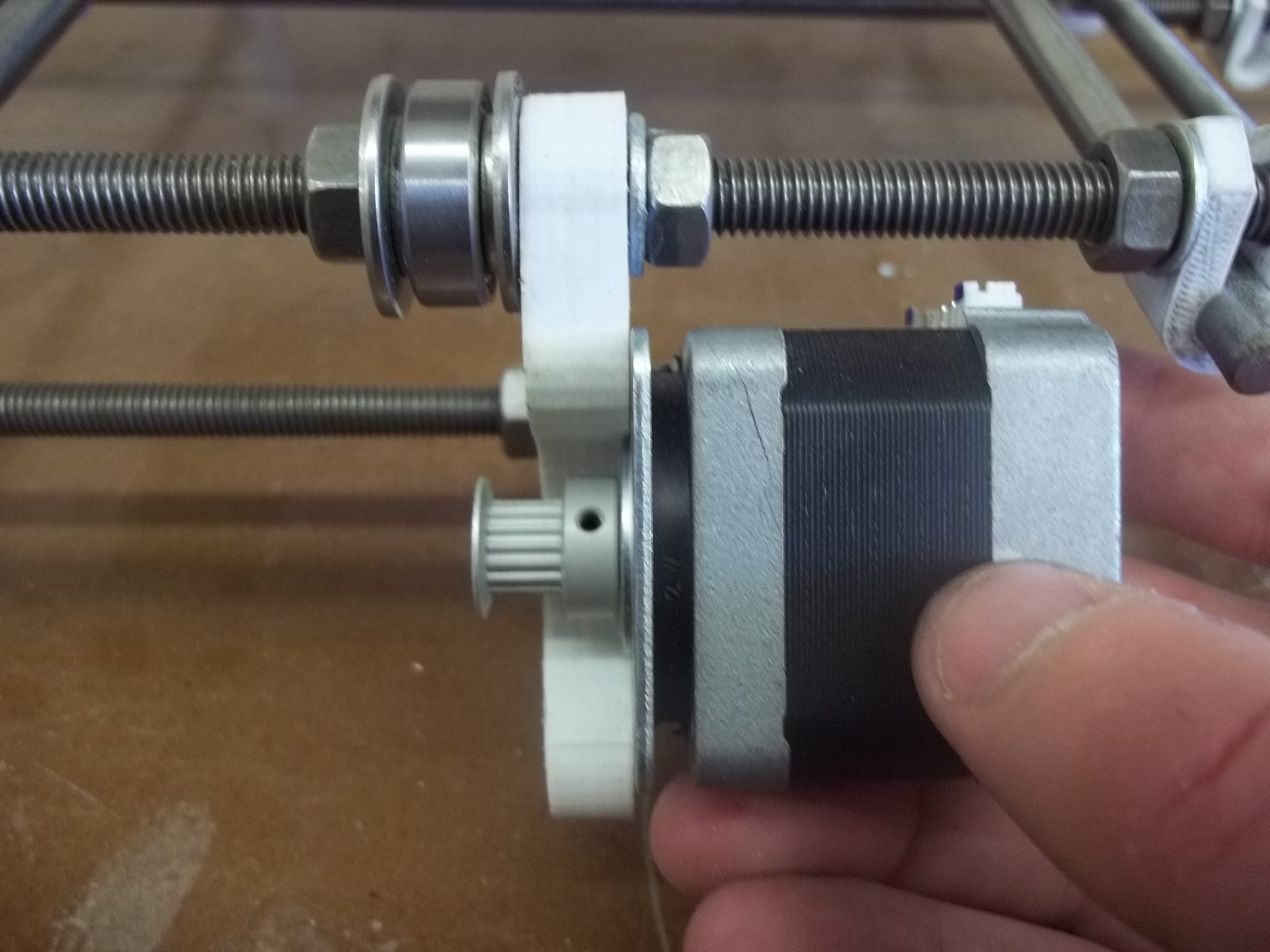
Once the print bottom plate is installed onto the bearing mounts, the stepper motor and belts are installed. My stepper motors have an unusual and apparently non-removable damper pre-installed on them, which shortens the shaft length a little bit. I had to mount pulleys hanging off the shaft just a little bit to line up with the belt, but it should be OK.
Installing the belts
I chose to mount my belt straight down the middle of the Y axis. However, since I used a pretty thin piece of plywood (1/8″) for the print bottom plate, the belt was a bit higher up than it should’ve been. I used a rod clamp as a spacer, which will cause some small problems later when I try to mount the print bed. I may upgrade to 1/4″ plywood in the future if I have problems.
[flickr-gallery mode=”photoset” photoset=”72157633666966682″]
X axis
The X axis was super easy to assemble – all I needed to do was slide two smooth rods into a plastic end piece, slide on the bearings and the Quick Fit X Carriage body, then add another printed end piece to the other end of the smooth rods.
Notes about the Quick Fit X Carriage
Unlike the stock Prusa i2 X carriage, the Quick Fit X Carriage actually slides onto the smooth rods, so it cannot be lifted off the axis without disassembling it entirely. It does, however, allow for a variety of really neat extruders made by RichRap, which seemed worth it to me. The LM8UU bearings are fastened to the carriage using zip ties.
Improved X Ends
I used these nice improved X ends from jonaskuehling and am very happy with them. They have a nice LM8UU bearing clamp and set screws for the smooth rods. I highly recommend these instead of the stock Prusa i2 X ends.
[flickr-gallery mode=”photoset” photoset=”72157633704362920″]
Z axis
Compared to the other two axes, the Z axis is the most complex, but not too terribly difficult. It requires that two smooth rods be mounted perfectly vertical and parallel to each other, which I’m not sure I’ve done correctly. I used a plumb bob and a spirit level as the build manual outlines, but I haven’t hooked up the electronics yet to test the up/down travel smoothness. It seemed pretty easy to do, which makes me suspicious :P
Installing the stepper motors
Once the smooth rods are installed, two stepper motors are installed at the very top of the frame, pointing downward. Instead of fastening these to the frame using screws, I chose to use zip ties, which should help to decouple any excessive wobble from the rest of the machine.
Installing the X axis assembly
Using a really simple block clamp, threaded rods are attached to the stepper motors. To my surprise, the entire X axis assembly moves up and down along these threaded rods (and the smooth rods) using a single hex nut on each threaded rod! This makes me very wary of potential backlash problems and makes me think of some obvious upgrades that I may consider in the future. ACME leadscrews, leadscrew nuts and spring tensioners could all improve the performance of the Z axis, if I need to.
[flickr-gallery mode=”photoset” photoset=”72157633703023389″]
Next steps
The only things left to assemble before calibrating and fine-tuning the machine are the extruder and the print bed. I have tried to build them both already but ran into some problems.
I was struggling with getting the correct gears and hot end mounting hardware for the extruder, which I should be able to get fixed pretty soon. And I couldn’t mount the print bed because the M3x20 screws needed for the rest of the machine are not long enough to reach my print bottom plate. I think I’ll tackle each of these issues separately and write up blog posts about what I did to make it all work.
Once I’ve solved these issues, I’ll be able to wire everything up to my RUMBA electronics board and start testing!
I’ve run out of filament to make the paste extruders that I wanted to use, so I’ll need to order some more and get those printed ASAP. I’m hoping to be printing with paste within a month or so!