ExtraCore RST – cheap, tiny Arduino-compatible board variant
For probably about a year now, I’ve been dying to find an Arduino-compatible board that I can install into old projects and not need to think about the cost involved. Typically, a brand-new Arduino Uno or Duemilanovae can cost anywhere between about $20 and $30, not including any of the other required components like the power supply or parts for your specific project. For education, prototyping and experimentation, this is fantastic – build your idea, document it, then move on. But when you know what you’re doing, and want to create a piece that is meant to be more-or-less permanently installed someplace, or you just want to keep it functional for inspiration, it’s not cost-effective or smart to install / sacrifice a complete Arduino board each time. There are plenty of projects that I’ve done where the Arduino is by far the most expensive component in it!
About the ExtraCore
 A few months ago, I came across a really sweet Kickstarter by a guy named Dustin Andrews showing a super small, super minimal, Arduino-compatible board designed exactly for this purpose. I came across the Kickstarter after it was funded, so I wasn’t able to acquire any that way, but he does offer the boards in kit form or assembled over at Rugged Circuits. The kits and assembled boards are very fairly priced, so please consider buying at least one to support him! Personally, I wanted to gain some experience in basic PCB manufacturing and SMD board design, so I wanted to see how hard it would be to do it all myself :)
Modifying it for my applications
Being an open-source project (thanks for that, Dustin!), the schematics and board files were made freely available, so I grabbed them and checked them out. I noticed that a low-pass filter was implemented for the AVCC pin of the ATmega328, as recommended by the chip’s datasheet. I’d be willing to bet that this may result in more accurate analog input readings, but I was curious about how the board would perform without it, especially considering that the precious board space could be used for something that I might use more. I also took the liberty of cleaning up the schematic a little bit, just to make it a little more pleasant to view :)
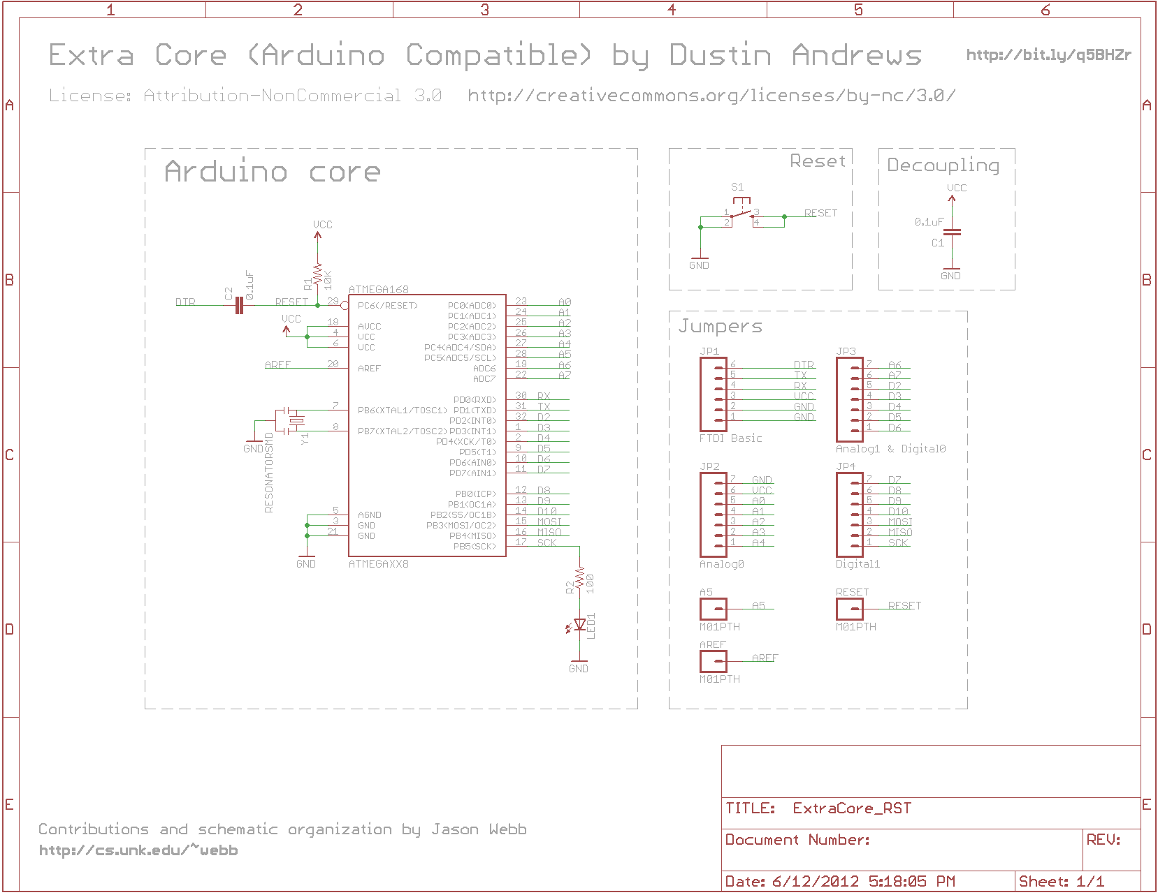
 When I removed the low-pass filter, I noticed a good amount of space open up on the board, and wondered what I could put there that I could really use. I figured a small tactile reset switch would be helpful, so that I didn’t have to manually cut power and re-apply every time I needed to push a new sketch to the board. Another great thing to have in this location, instead of the reset switch, would be a 5V regulator so that you can run your ExtraCore off of a 9V battery or a LiPo battery pack. Maybe I’ll do another run later to try that out :)
Get the source files on Github
Required parts (BOM)
One of the coolest things about this board is its astonishingly low parts count. In previous projects, I realized that it is remarkably easy to set up an ATmega328 microcontroller to be “Arduino-compatible”: a 10k pull-up resistor on the reset pin and a 16MHz resonator. In fact, if you don’t mind running your Arduino at 8MHz (like the Arduino Pro or Lilypad series), you can skip the resonator entirely and rely on the ATmega’s internal resonator!
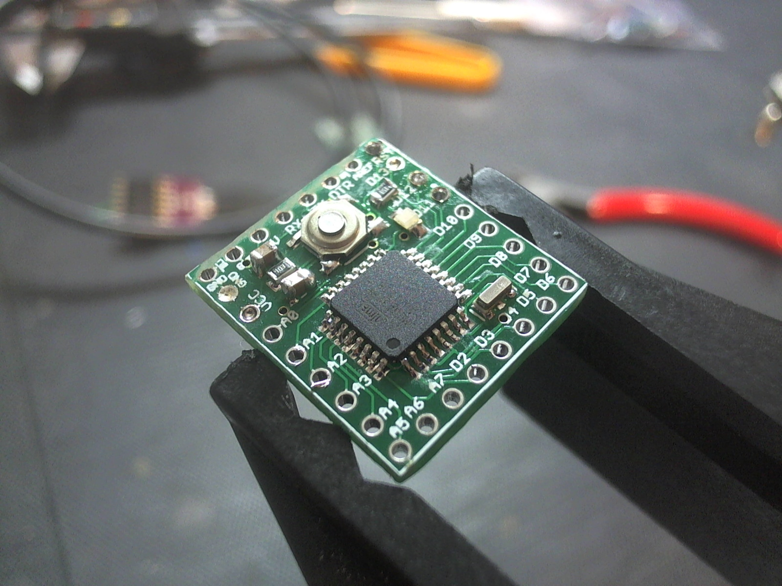
All told, the ExtraCore RST board only requires eight parts, which includes the tactile reset switch and an on-board green LED connected to digital pin 13, just like the full-size Arduinos! Here’s the full bill of materials:
Panelizing and manufacturing the PCBs
 Of course, one must have physical PCBs to install the parts onto, and this is the part of the project that I’m most excited about. Thanks to the extremely small footprint of the ExtraCore board, and the availability of cheap, hobby-level PCB manufacturing services like Seeed Studio’s Fusion PCB service, anyone can actually get quite a lot for very little money!
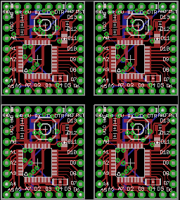
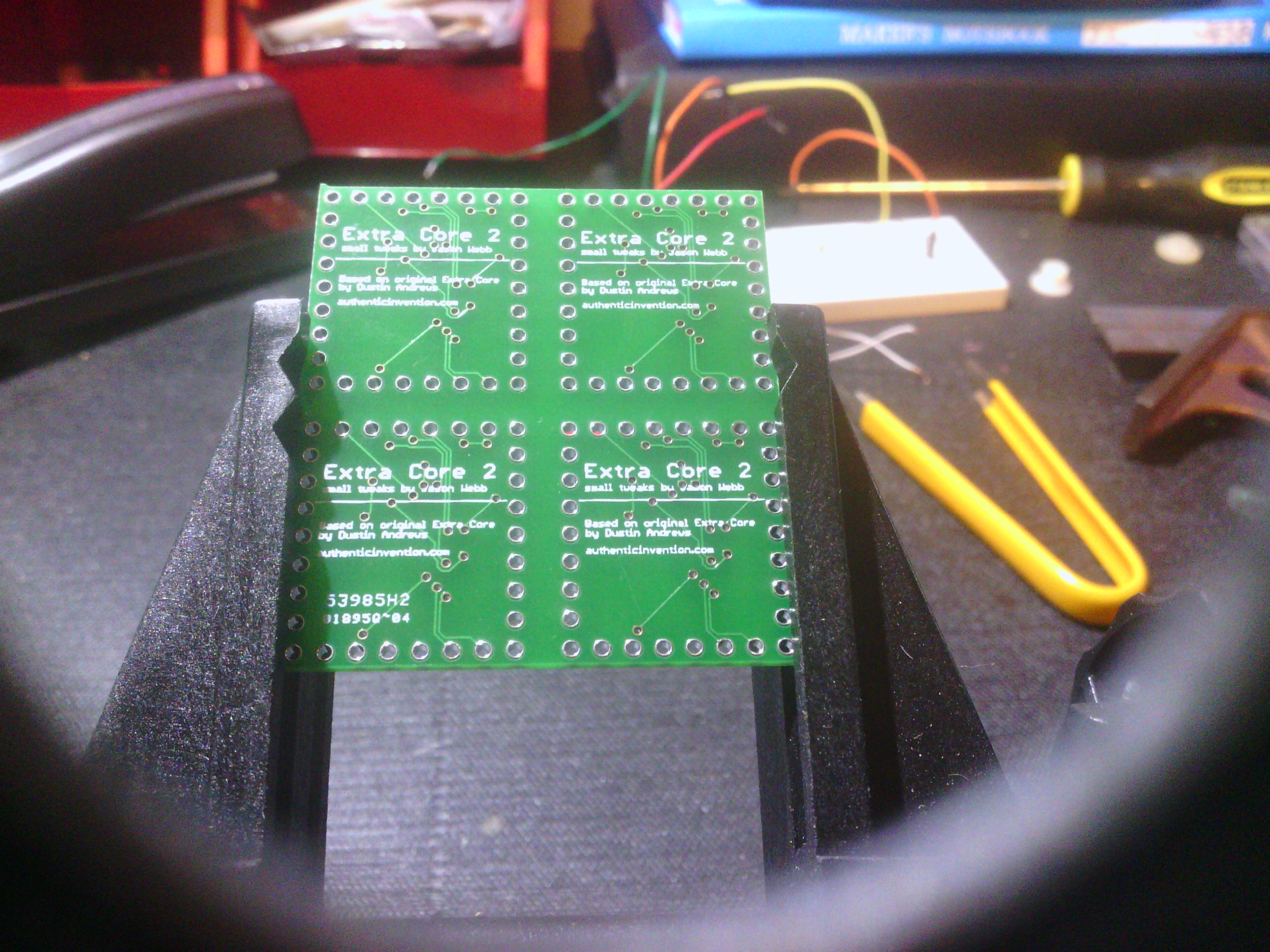
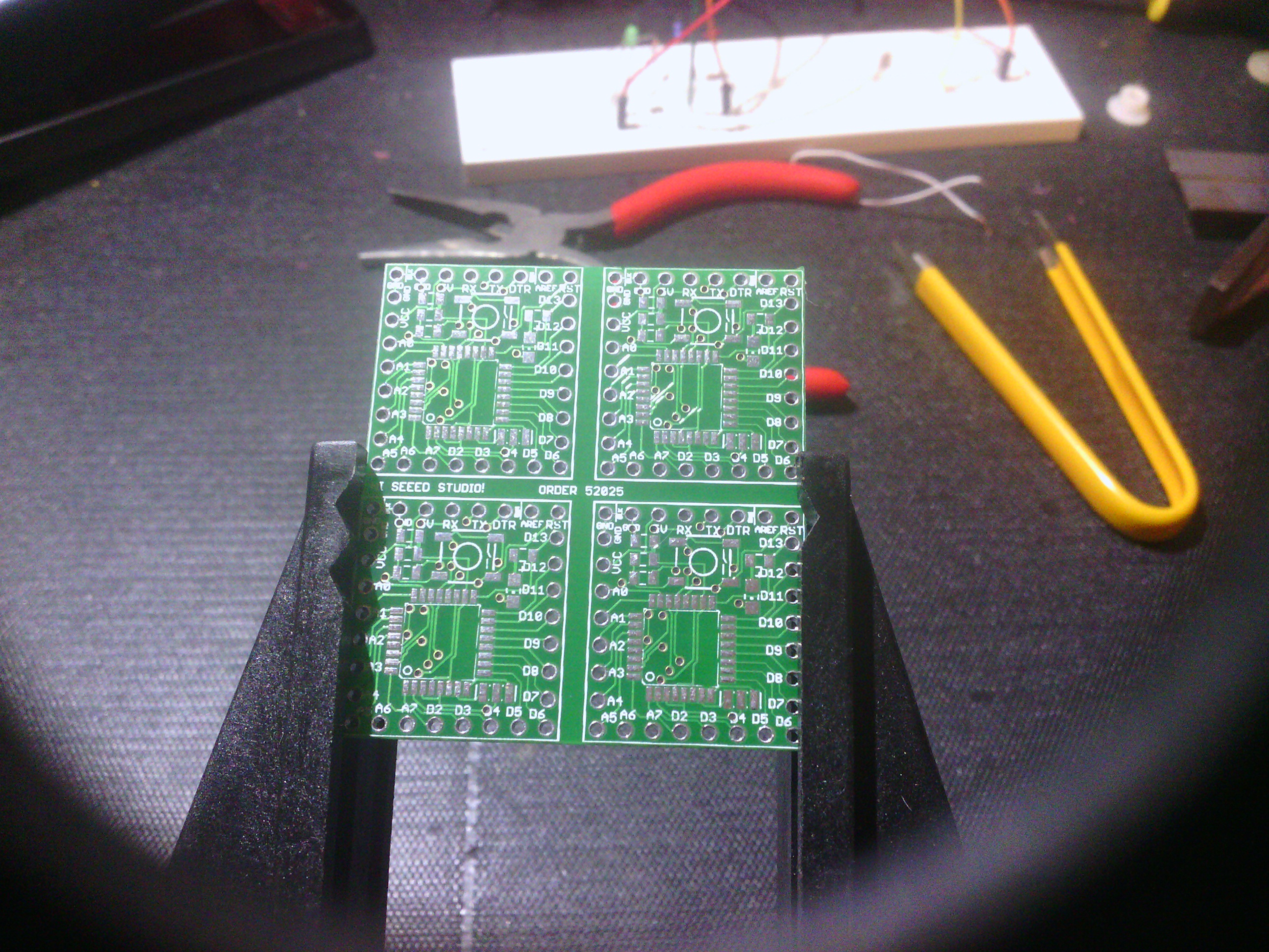
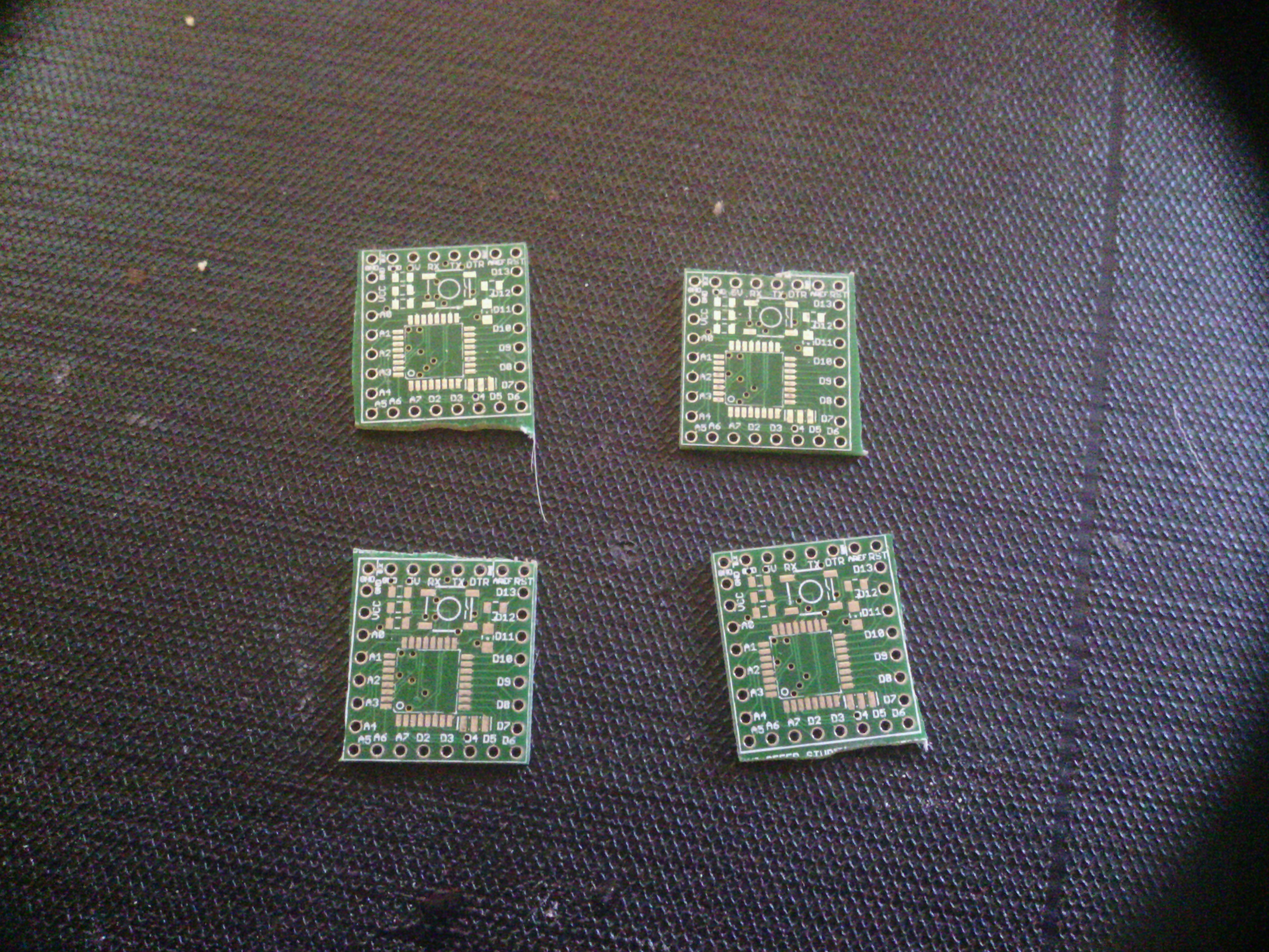
Seeed Studio charges only $9.90 for 10 boards under 5cm x 5cm in size. Even better, they allow for panelizing, which means if you can fit your board multiple times into a 5cm x 5cm square, they will only charge you for 1 board overall. Other PCB services likely offer similar specs, but I only have experience with Seeed so far. I was able to fit four ExtraCores into a single square smaller than 5cm by 5cm (with some spacing to allow for a saw blade).
My panelized .brd file is freely available at the aforementioned Github repo, so feel free to grab it if you want to order some PCBs somewhere!
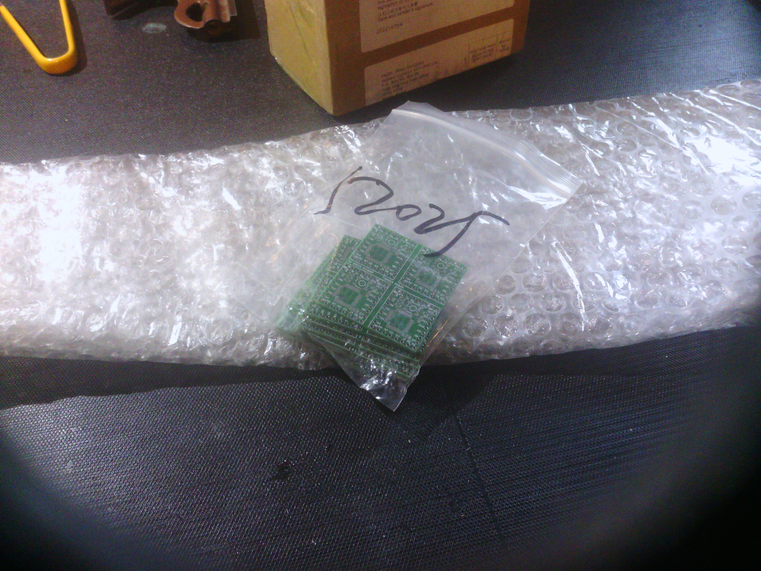
Because Seeed Studio charged me only $9.90 for 10 boards, and each board had 4 ExtraCores on it, a single order yields 40 ExtraCore boards! For me, shipping was a mere $4.10, which means that all in all, each ExtraCore board (without the parts) cost me $0.35 to make. Let me say that again:
Each board only cost me $0.35!
Based on previous research, I was expecting the PCBs to take about 2-3 weeks to be manufactured and shipped, which felt completely reasonable to me for the total cost of $14.00. I placed my initial order on 5/30, and to my surprise, saw that it was manufactured within a week of the order! The order shipped on 6/6, and arrived on my doorstep on 6/16 – a total turnaround time of 17 days.

Depanelizing and finishing the PCBs
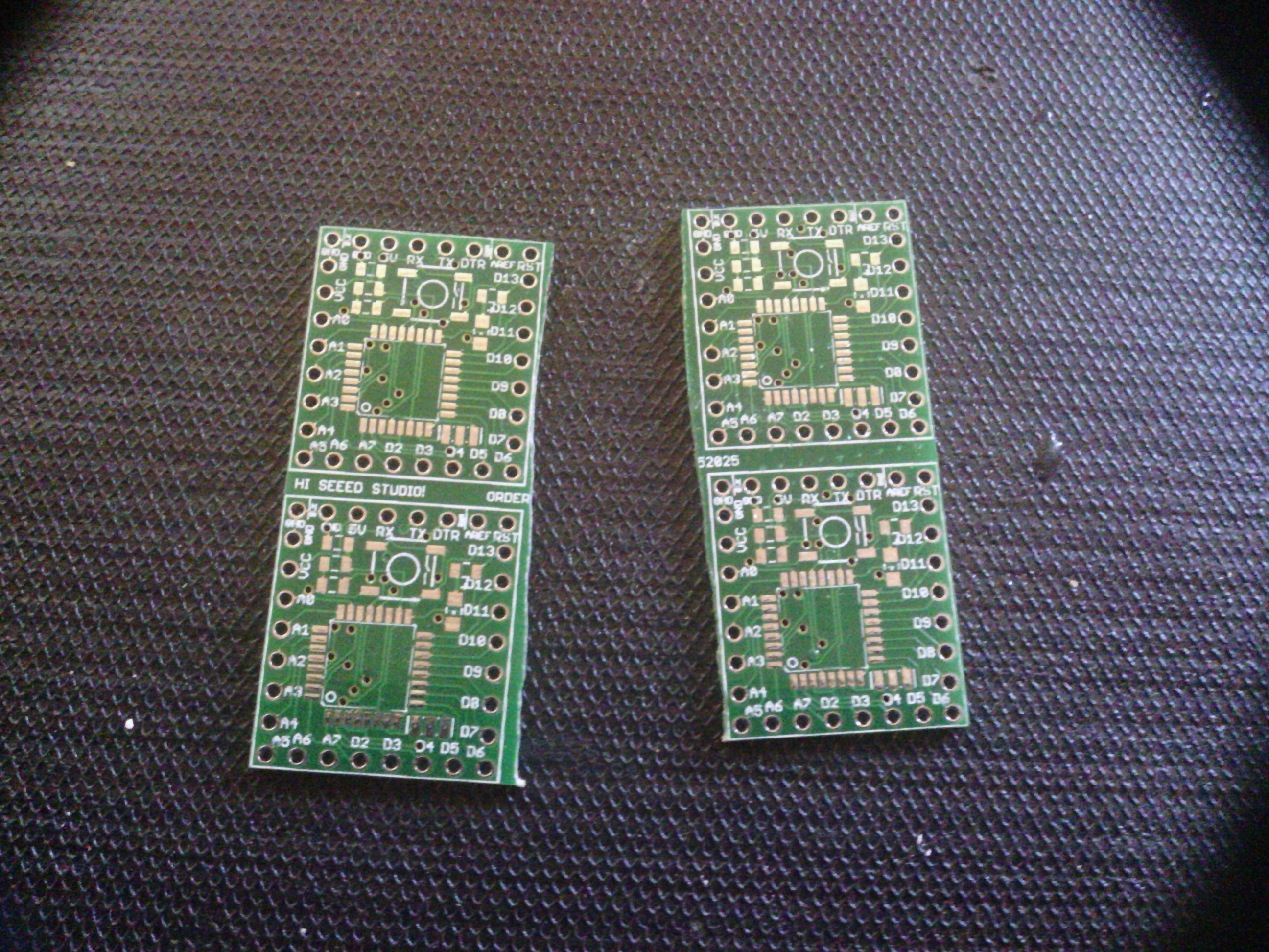
One stipulation of the Seeed Studio PCB service is that if you do decide to panelize your boards, you need to depanelize them yourself. In other words, although I placed four separate ExtraCores onto a single board, I will still receive 10 boards and will have to cut them apart myself. Again, for the price this felt completely fair!
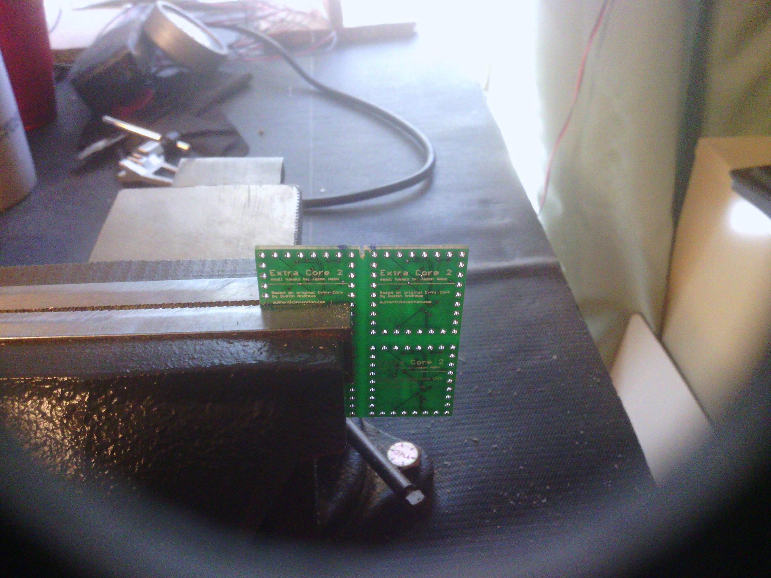
Since circuit board material (FR4) is essentially fiberglass, it will tend to wear down dry tools like table saws and band saws, so be aware that your blades will wear out pretty quickly if you use one. I have heard that wet cutting tools like tile cutters work well, but I didn’t want to try to track one down just for this little project. I pulled out my trusty coping saw and manually sawed these boards. I would actually recommend this method if you only need to make a couple cuts – my coping saw made very quick work of my boards!
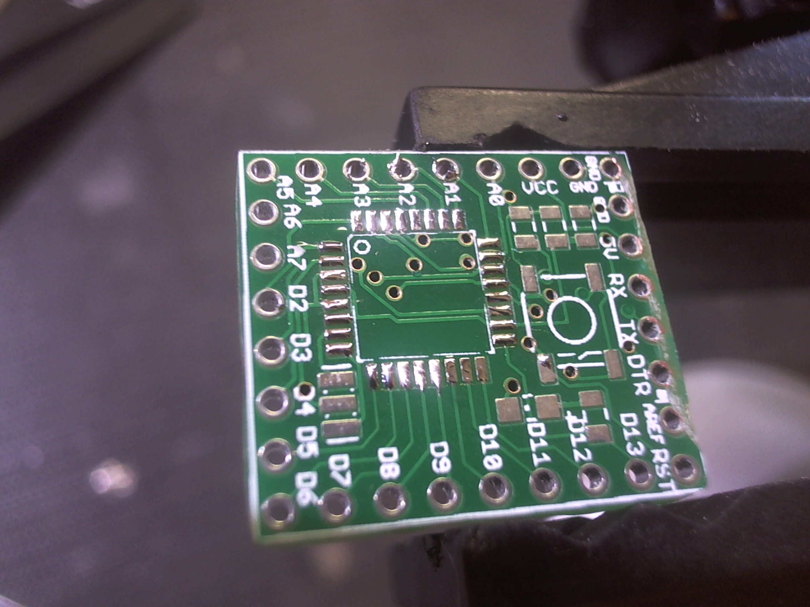
After depanelizing, you may have some rough edges, and you can just take a rotary tool with a sanding bit to even it out. Totally not necessary, but I did it anyway.
Assembling the boards
All of the parts for this board are surface-mount, which have a reputation for being pretty hard to work with. But with a little bit of soldering experience, its not bad at all really! To make things a little bit easier, I used 0805 sized parts, just like the original ExtraCore. If you plan on making tons of these little boards, or plan on selling them on an on-going basis (which I believe is not allowed under the license used by the ExtraCore), you can opt to do this stage in many different ways. Griddles, hot plates, toaster ovens and more can be used. But I didn’t want to get into it that far, so I just used my soldering iron. Here’s a few tips I’ve come up with for doing this:
- Tin the pads and parts before placing, and apply flux if you’re nervous.
- Place the parts slowly and carefully: tweezers can be very helpful here
- Solder one of the pins to hold it in place, then do the rest.
- A PCB vise like the PanaVise Jr. can also be a big help here, though not necessary if you’re used to other methods.
- If you have a chisel tip for your soldering iron, it will make it a little easier, especially with the 32-TQFN ATmega328 package.
- When dealing with parts without exposed pads (like the ceramic resonator), lightly tin the part and liberally apply solder to the PCB pads. The PCB pads should be slightly larger than the part itself, so that when you place the part, you can reflow the solder by touching the iron to the exposed part of the pad.
Tips for soldering the 32-TQFN ATmega328P
Let’s not kid ourselves here, the 32-TQFN package is a tough one to solder. But take my word for it that it IS possible to do! You just have to realize that you cannot approach it the same way you would through-hole parts, or even discrete SMD parts! Do NOT just slap solder on and keep heating the pads until it flows. You may not get it right the first time, and that’s OK. After destroying the chip in my first attempt, I learned a couple things I wanted to pass on here:
- Begin by lightly tinning every pad on the PCB
- Lightly tin each pin of the chip before placing it.
- Place the chip on the board gently, using tweezers.
- Gently touch one pin to reflow its solder and the solder on the pad below it, creating an ‘anchor point’.
- Keep using your tweezers to make sure the chip is as perfectly centered on the pads as you can get it (check ALL the sides).
- Solder one pin on the opposite side you started to create a second anchor point.
- Make sure the chip is still well-centered. If not, undo one of the anchor points and reposition.
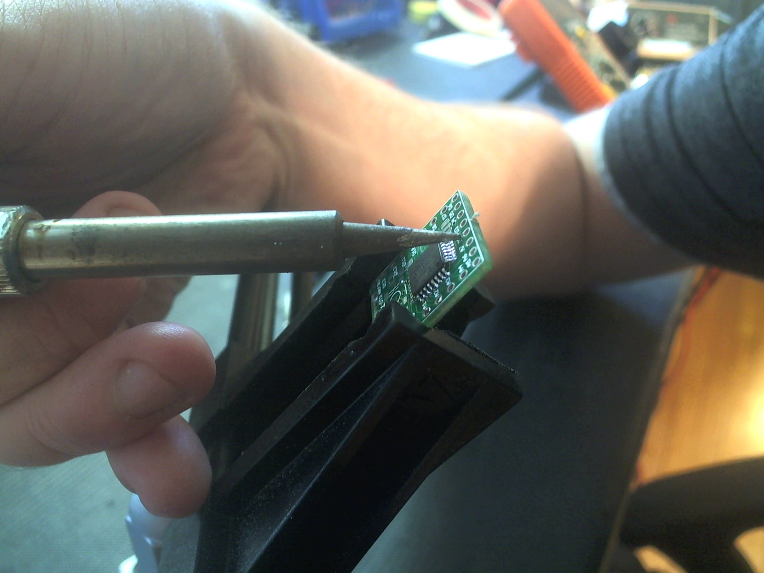
- Tilt your board so that you are look down at a steep angle (refer to this picture).
- Align your soldering iron so that it is vertically aligned with one pin, and one pin only, with it’s angle matching the angle of the pin (refer to this picture).
- Gently, but confidently, push the pin into the pad below it in one smooth motion. If you do it right, the solder on both the pin and the pad with flow, then wick together. Releasing the pin should leave it right where you want it.
- Pull out your multimeter and test for continuity by touching one lead to the pad, and the other lead to the top of the pin, close to the chip body (refer to this picture).
- For good measure, also test continuity by touching one lead of the multimeter to another part of the board that should connect to the pin you’re checking (like a hole around the edge or ground), and tap the corresponding pin of the ATmega328 (refer to this picture).
- Take your time and do the rest of the pins, one by one. Yes, I recommend testing for continuity each and every time you solder a pin – at least until you are able to tell by sight whether its connected. Go slow, and try not to build up too much heat on the chip. If you get bridges and/or start getting frustrated – stop. These chips can and do get fried from excessive heat buildup, so always keep a watchful eye (and finger) on the chip while soldering.

Burning the bootloader
 Once assembled, the Arduino bootloader needs to be loaded onto the ATmega328 before any Arduino sketches can be uploaded. This is actually very easy to do, and several good tutorials are out there to help you figure it out:
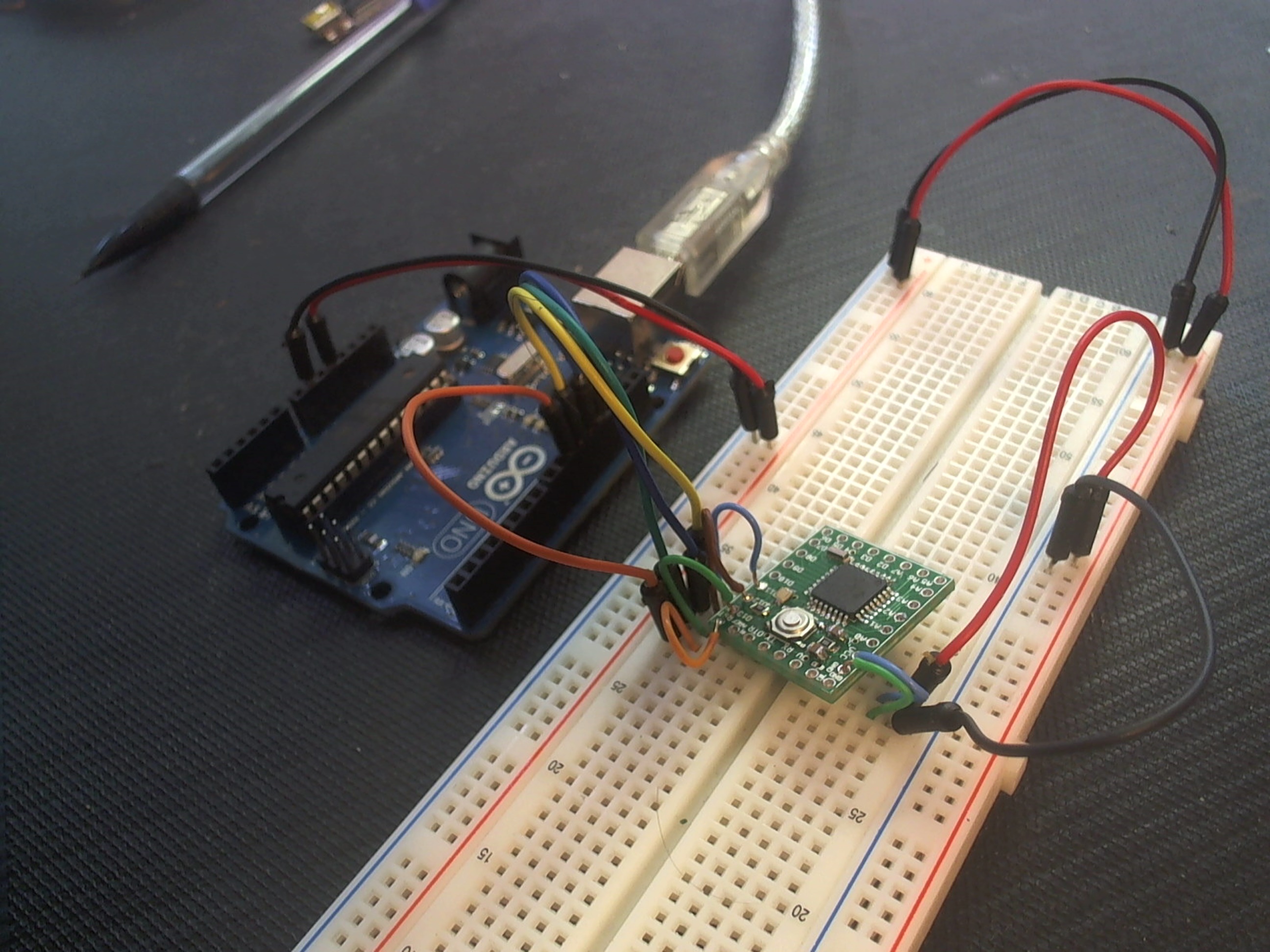
Here’s all you really need to know:
- Load the ArduinoISP sketch onto an Arduino-compatible board
- Connect the ExtraCore’s RST pin to the Arduino D10
- Connect ExtraCore D11 to Arduino D11
- Connect ExtraCore D12 to Arduino D12
- Connect ExtraCore D13 to Arduino D13
- Connect ExtraCore 5V and GND to appropriate pins on the Arduino
- Change the Programmer in your Arduino IDE to “Arduino as ISP”
- Click Burn Bootloader
- After a few seconds, the RX and TX lights on the Arduino will start flashing furiously, and the on-board LED on the ExtraCore should also flash. This process will take about 30-40 seconds.
Uploading a sketch
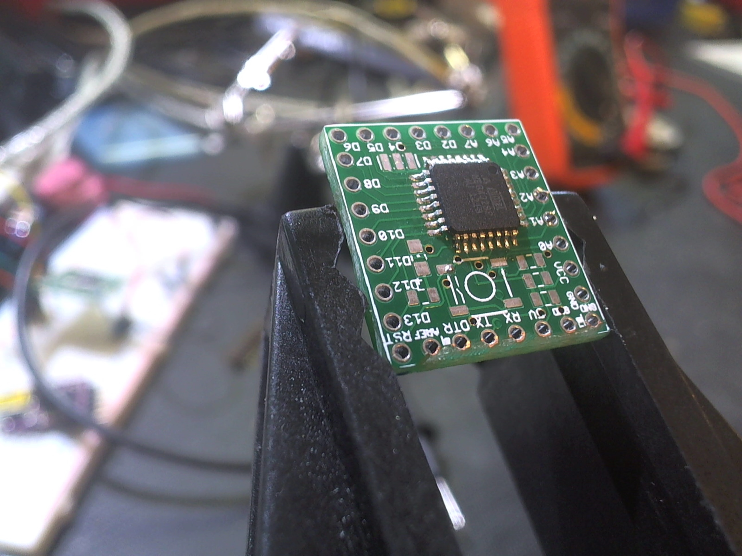
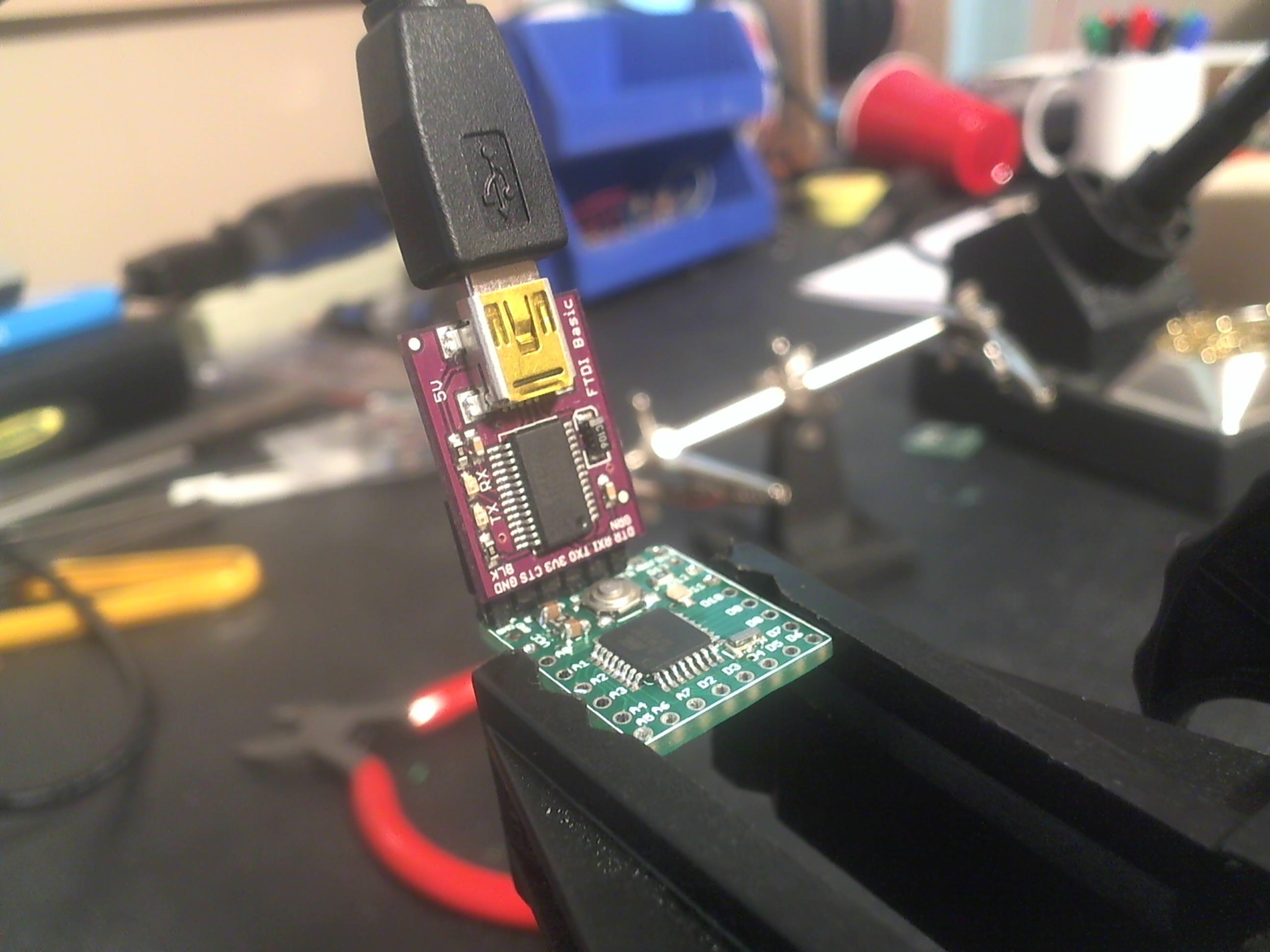 With the Arduino bootloader burned to the ATmega328, sketches can be uploaded anytime using an FTDI cable or FTDI breakout board. To my knowledge, any Arduino sketch that would run on an Uno or Duemilanove will work on the ExtraCore. To make sure the board works, and that the bootloader is correctly burned to the ATmega328, I uploaded the ubiquitous Blink sketch to the board. Select “Arduino Uno” from the Board Type menu and upload just the same as if a normal USB-based board were connected.